DJI N3 Flight Controller - Reference Material
Data and Software Downloads
Basic Knowledge
Hardware Components:
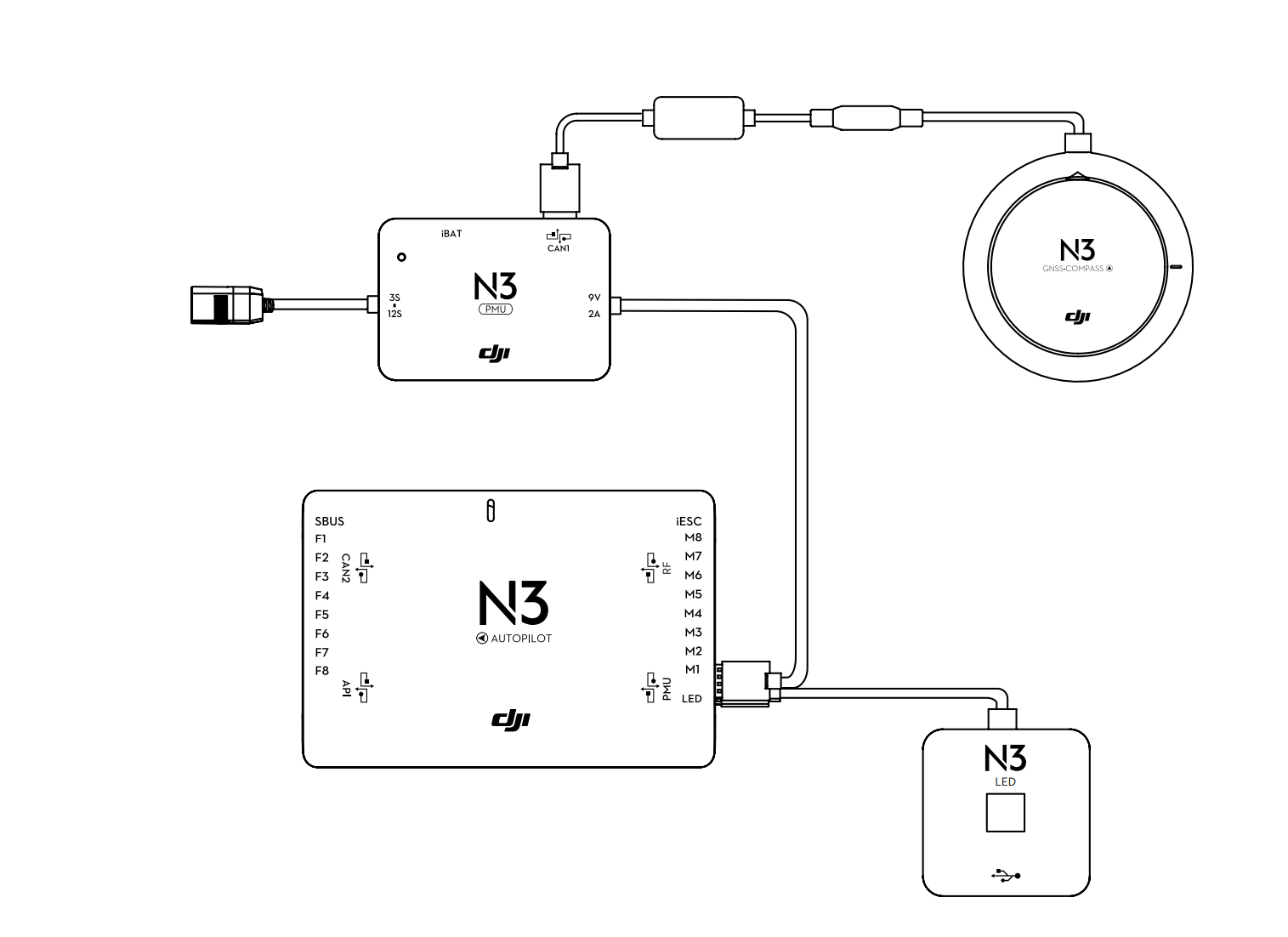
- Main Controller (Dual IMU, Data Recorder, and Barometer), with CAN1 connecting to the GNSS-Compass module and DJI devices, and CAN2 connecting to SDK devices; M1 - M8 connecting to the aircraft ESCs, and can communicate with DJI Intelligent ESCs through the iESC port.
- GNSS-Compass module, including GPS/GLONASS dual-mode receiver and compass.
- Power Management Unit (PMU).
- LED module.
Flight Modes:
- P: Positioning mode, using GPS module or vision positioning system for precise hovering.
- A: Attitude mode, without GNSS and vision positioning system, only provides attitude stabilization, and can return home if GPS satellite signal is good.
- S: Sport mode, based on automatic positioning mode, with increased sensitivity, maximum attitude angle of 45°.
- G: Gentle mode, in this mode, the aircraft moves more slowly, recommended for beginners.
- M: Manual mode, without GNSS and vision positioning system, no attitude stabilization, no attitude angle limitation.
Return-to-Home Function: Intelligent/Low Voltage/Out of Control Return-to-Home
Protection Functions: Out of Control Protection/Low Voltage Protection/Height and Distance Limitation/Special Area Flight Restriction/Power Output Loss Protection (applicable to hexacopter and above)/Power Protection/Built-in Dual IMU/Built-in Data Recorder/Heading Lock/Return-to-Home Lock
Flight Characteristics: Due to hardware differences, maximum wind resistance is 10 m/s, vertical hovering accuracy is ±0.5 m, horizontal hovering accuracy is ±1.5 m, maximum yaw angular velocity is 150°/s.
Hardware Installation

The main controller should be facing up and parallel to the aircraft body, with the recommended direction towards the front of the aircraft (if it is in a different direction, it needs to be set in the software), and installed as close to the center of gravity of the aircraft as possible.
The LED module can be installed on the lower side of the aircraft body for easy observation of its status during flight.
Pay attention to the heat dissipation of the PMU module.
Hardware Debugging
Compass Calibration
- Quickly toggle the P/A mode switch 3 times, at this time the yellow light will be on constantly, entering the calibration state.
- Rotate the aircraft horizontally 360°, at this time the green light will be on constantly.
- Turn the aircraft upside down with the nose facing down, and rotate it horizontally 360°.
- At this time, the lights will blink normally, indicating the completion of calibration. If the red light is blinking, calibration needs to be done again.
Parameter Settings
- Basic Sensitivity (Pitch/Roll/Yaw): As large as possible, but not too large, as excessive feedback can cause high-frequency shaking during hovering; on the other hand, if it is too small, it will result in longer response time (similar to network latency in games) and shaking.
- Throttle: As large as possible, but if it is too large, takeoff and landing will be too fast and unsafe; if it is too small, it will result in slow takeoff and landing, and it will also affect the above parameters.
- Power Bandwidth: Varies depending on the aircraft, if it is too small, it will result in slow response and high-frequency shaking during hovering (insufficient power); if it is too large, it will overcorrect and cause slow oscillation when returning to center.
- Brake:
- Attitude Sensitivity (Brake/Attitude): The smaller the attitude sensitivity, the slower the attitude command follows the remote control command, and the attitude response is smoother; the brake sensitivity describes the speed of braking, the smaller it is, the smoother the braking process and the longer the braking distance.
- Attitude Sensitivity: The larger the attitude sensitivity, the more rapid the attitude response, and the smaller the sensitivity, the slower the response.
Este post está traducido usando ChatGPT, por favor feedback si hay alguna omisión.