ZenDriver - High-Performance Motor Driver
—— Based on Version 5.1 Release
Project Repository: linyuxuanlin/ZenDriver
Basic Specifications
- Input Voltage: 7.2 ~ 20 V
- Output Current: 0 ~ 68 A
- Provides 5V 1.5A power output for controller use
- Protection Features: Integrated reverse connection protection, opto-isolation circuit
Interface Definitions
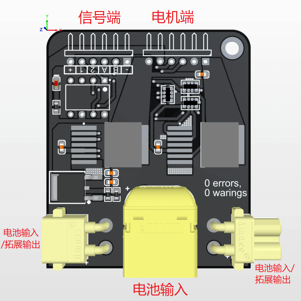
From left to right on the motor side, the pins are: M-, 5V, Encoder A, Encoder B, GND, M+, corresponding to motor connections, suitable for direct motor attachment.
From right to left on the signal side, the pins are: GND, Encoder B, Encoder A, IN2, IN1, 5V. Note: The 5V port can supply power to a microcontroller (up to 1.5 A).
The three interfaces on the power input side are common, with the middle one typically used for battery connection, and the adjacent two interfaces for expanding power to other driver boards.
User Guide
Direct Power Supply Testing
- Connect a 7.2 ~ 20 V battery for power supply.
- Connect the motor.
- Use the 5V from the signal side to connect IN1 and IN2; the motor will rotate in both forward and reverse directions.
Microcontroller Connection Testing
- Connect a 7.2 ~ 20 V battery for power supply.
- Connect the motor.
- Connect signal side GND to microcontroller GND, and the 5V port to the microcontroller's 5V.
- Pins IN1 and IN2 are connected to the microcontroller's PWM ports.
- Debug using code.
Original: https://wiki-power.com/ This post is protected by CC BY-NC-SA 4.0 agreement, should be reproduced with attribution.
This post is translated using ChatGPT, please feedback if any omissions.