RobotCtrl_Power - Power Supply Board
Project Repository: linyuxuanlin/RobotCtrl/RobotCtrl_Power
Project Online Preview:
Note: This project is included in RobotCtrl - STM32 Universal Development Kit.
Schematic Design
The main functions of RobotCtrl_Power are as follows:
- 24V power input (theoretically accepts 15-40V)
- Battery power conversion to 12V/5A regulator (with enable switch and indicator light)
- Battery power conversion to 5V/5A regulator (with enable switch and indicator light)
- Reverse polarity protection (P-MOS)
- Overvoltage protection (activates above 30V)
- Battery power output, 12V power output, and 5V power output interfaces
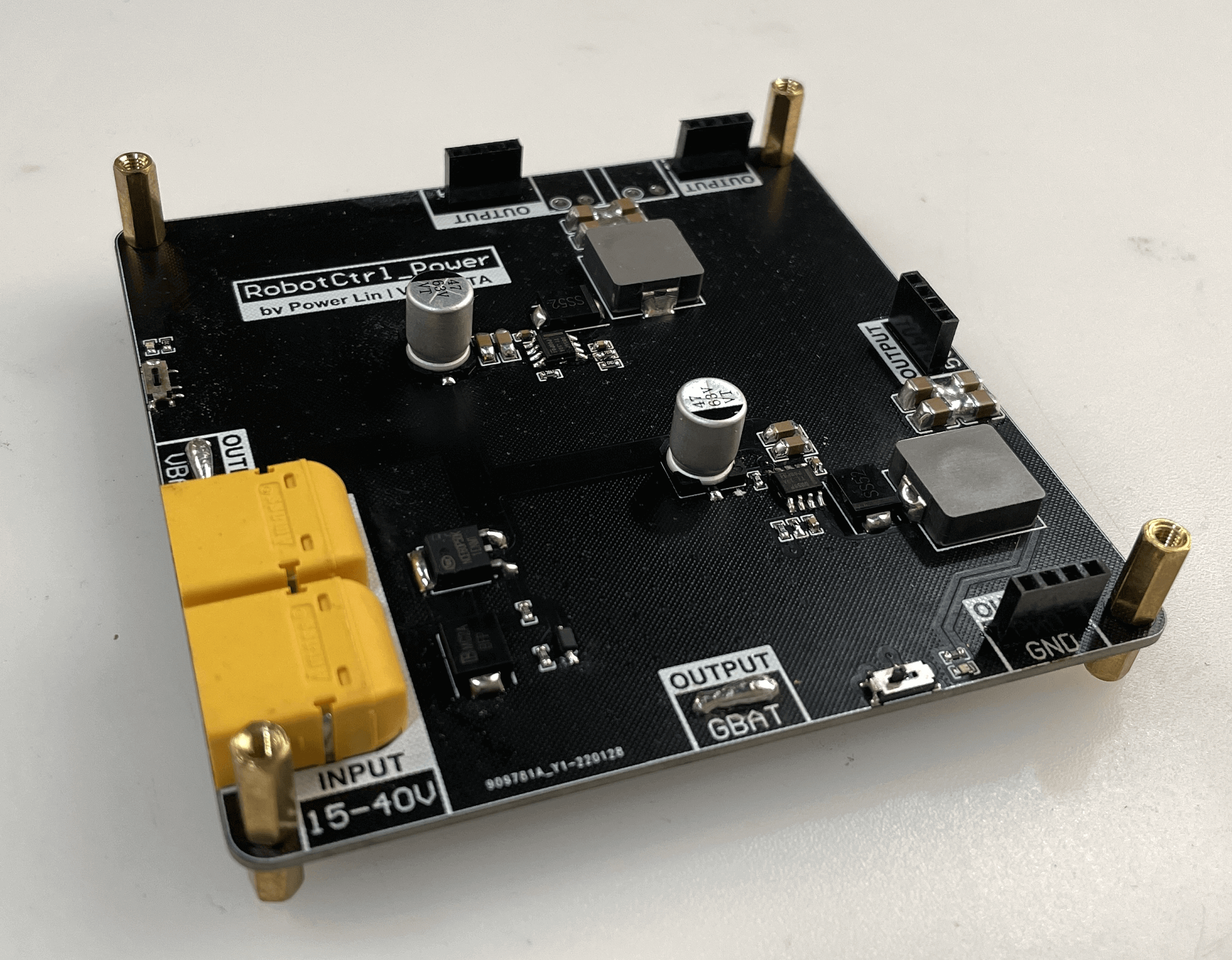
Power Input
Two XT60PW-M connectors are used for power input, providing dual power backup input (or one input and one output), and two rows of header pins for output testing.
Reverse polarity protection is implemented using a P-MOS, even though XT60 is designed to prevent reverse insertion, it's essential to prevent scenarios where positive and negative power lines are mistakenly soldered in reverse. When reverse polarity occurs, the P-MOS will not conduct, and power will not be supplied to the system. For more information on reverse polarity protection design, please refer to the article Designing Reverse Polarity Protection Circuits.
Instantaneous overvoltage protection and ESD protection are provided by TVS diodes. When voltage greater than 30V is applied, the TVS diodes will shunt the excess voltage to protect the downstream system.
12V and 5V Voltage Regulation Circuits
The 12V and 5V voltage regulation circuits use two TI LMR14050 DC-DC Buck solutions, each capable of carrying a maximum of 5A current. For detailed design information, please refer to the article Power Solution (Buck) - LMR14050.
Additionally, each path is equipped with an enable switch and a power indicator light.
Power Output Ports
VBAT, 12V, and 5V outputs each use a pair of 4-pin header pins, and the 12V output includes an additional KF2EDGR-3.81 connector for powering special sensors.
PCB Design
For the PCB layout of RobotCtrl_Power, it's important to place the voltage divider resistors of the feedback network as close as possible to the FB pins of the chip. The Vout sampling path should minimize noise generation (inductor-diode loop), preferably routing it through vias to a shield layer. Place the inductor near the SW pin to reduce magnetic and electrostatic noise. Ground connections for diodes, input, and output capacitors should be as small as possible and ideally connect to the system ground at a single point to minimize conducted noise in the system ground layer. Output capacitors should be placed as close as possible to the nodes of the inductor and diode, with short and wide traces to reduce conduction and radiation noise and improve efficiency.
RobotCtrl_Power's PCB top and bottom layers carry signals and power, with two ground planes inserted in between to enhance signal and power integrity.
Hardware Testing
- Reverse Connection Test: Check if the system can remain off when the input voltage is connected in reverse.
- Enable Switch and Power Indicator Light: Verify if the system can operate correctly.
- Outputs: Evaluate whether the 12V/5V outputs meet the specified standards and assess the level of ripple.
This post is translated using ChatGPT, please feedback if any omissions.