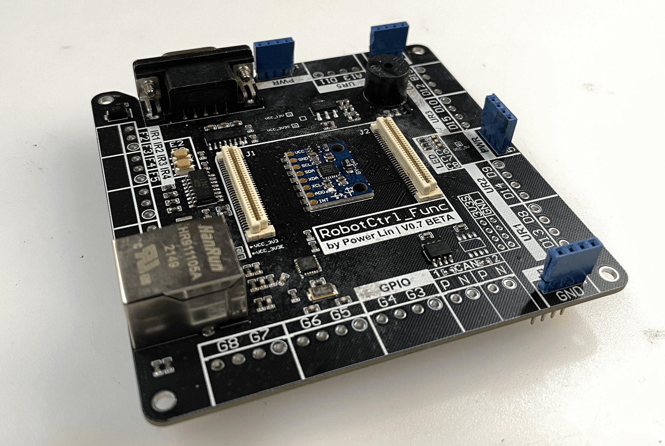
RobotCtrl_Func - Peripheral Expansion Board
Project Repository: linyuxuanlin/RobotCtrl/RobotCtrl_Func
Project Online Preview:
Note: This project is included in RobotCtrl - STM32 Universal Development Kit.
Schematic Design
The primary functions of RobotCtrl_Func are as follows:
- 12V power input, 5V power input/output, 3.3V power output (with test points)
- 5V to 3.3V voltage regulator circuits * 2 (for sensors/Ethernet, with test points)
- Ethernet communication circuit
- CAN communication circuits * 2
- Serial communication circuit (RS-232 and TTL levels)
- Buzzer circuit
- User buttons * 2
- User LEDs * 3
- MPU6050 attitude sensor module
- Infrared distance sensor interfaces * 4
- Ultrasonic interfaces * 5
- User GPIO interfaces * 6
- B2B connectors (with access to all IO)
- SW download interface
Power Supply
RobotCtrl_Func features 2 LDO channels, similar in principle to RobotCtrl_Core. One channel is used for external sensors, while the other is dedicated to the Ethernet circuit.
Ethernet Communication Circuit
Ethernet communication is based on an Ethernet PHY chip, using the RMII interface to communicate with the microcontroller. It communicates with external network cables through the RJ45 port, which has a built-in isolation transformer. The clock for the Ethernet circuit uses an external 25M passive crystal oscillator and requires independent power to reduce power interference. Here, the same low dropout linear regulator power supply scheme as the core board is used to power the Ethernet circuit separately. The principles of Ethernet communication can be found in the article HAL Library Development Notes - Ethernet Communication (LwIP).
CAN Communication Circuit
The CAN communication circuit is built around CAN transceiver chips, using differential voltage levels for transmission. The CAN protocol controller (e.g., microcontroller) is connected to the transceiver via serial lines (RX/TX), which are then converted into CAN signals (CANH/CANL) on the transceiver. The high-speed/silent mode is selected via the RS pin. A 120Ω termination resistor is required on the CAN bus to match impedance and reduce signal reflections. The principles of CAN communication can be found in the articles Communication Protocol - CAN and HAL Library Development Notes - Serial Communication.
Serial Communication Circuit
The RobotCtrl_Func board features an on-board RS-232 level serial communication circuit and additionally provides TTL level USART1/UART5 interfaces. For a detailed understanding of serial communication principles, you can refer to the articles Communication Protocols - Serial Communication and HAL Library Development Notes - Serial Communication.
The RS-232 communication circuit employs a TTL to RS-232 level conversion chip, which converts the TTL level of the microcontroller to RS-232 level. To enhance EMC performance, you can connect the DB9 connector shell pins to ground via TVS diodes. The TTL to RS-232 chip requires additional decoupling and bootstrap capacitors.
Buzzer Circuit
The buzzer circuit utilizes a 12V buzzer and can be controlled with a single transistor.
User Buttons and LEDs
For an understanding of the principles behind user buttons and LEDs, you can refer to RobotCtrl_Core. Further elaboration is not necessary here.
Attitude Sensor Module
The MPU6050 module can be directly mounted for use, and I2C interface is reserved for communication with the microcontroller. To learn about the principles of I2C communication, you can refer to the articles Communication Protocols - I2C and HAL Library Development Notes - I2C Communication (MPU6050).
Infrared Range Sensor Interface
The four-channel infrared range sensor interface circuit operates with 12V power and signals (NPN normally open type) from the infrared sensor. Therefore, 12V power is supplied from RobotCtrl_Power, and four optocoupler isolation chips are added to transmit high and low-level signals. When designing the optocoupler isolation circuit, the value of the current-limiting resistor must be calculated based on the current magnitude, ensuring that it falls within the triggering voltage range specified in the datasheet. You can refer to the article Basic Components - Optocoupler for an understanding of optocouplers.
Power Input Interface and B2B Connector
The power input interface for the peripheral expansion board consists of 4 rows of pins for connection to the bottom power supply board. The B2B connector is used to provide power and data communication to the main control board.
Hardware Testing
Power Testing
Power input (follow this procedure for all testing items):
- VCC_12V: Input via P1.
- VCC_5V: Input via P2 or J1_1/2.
- GND: Connect to external ground via P3, P4, J1_31/32, or J2_30/31.
5V to 3.3V Voltage Regulation (for sensors):
- VCC_3V3S: Measure if the voltage across C30 is 3.3V.
5V to 3.3V Voltage Regulation (for Ethernet):
- VCC_3V3E: Measure if the voltage across C26 is 3.3V.
On-Board Sensor Testing
User buttons:
- Configure PE2/PE3 as GPIO pull-up input mode. When a button is pressed, it should read a low level, and when released, it should be high.
User LEDs:
- Configure PC6/PC7/PC8 as GPIO output mode. Setting the pins to high will light up the LEDs sequentially, while setting them to low will turn them off.
MPU6050 Attitude Sensor Module:
- Measure if pin 1 of M1 module is at VCC_3V3S voltage to ground.
- Test the continuity of IO pins.
Buzzer:
- Measure if the positive terminal of BUZZER1 is at VCC_12V voltage to ground.
- Configure PC9 as GPIO output mode. Setting it to high will activate the buzzer, while setting it to low will silence it.
Serial to RS232: [Translation ends here, as the text is cut off]
Sure, here's the translation of the text into English while maintaining the original markdown format:
- Check if both ends of C3 have the voltage VCC_3V3S.
- Run the test program using the PB10/PB11 pins for testing.
CAN Bus Communication:
- Measure the voltage at both ends of C10/C13 for VCC_5V.
- Run the test program (loopback test) using the PD0/PD1 and PB12/PB13 pins for testing.
Ethernet Communication:
- Check if IC2_9 to ground has the voltage VCC_3V3S.
- Check if VDD1A/VDD2A to ground has the voltage VCC_3V3E.
- Run the test program to test Ethernet communication via the RMII interface.
Interface Testing
Infrared Range Sensor Interface:
- Measure whether the 1st pin to ground of connectors J16/J17/J18/J19 has the voltage VCC_12V.
- Configure PF2/PF3/PF4/PF5 as GPIO pull-down inputs. Externally set IR1/IR2/IR3/IR4 to a high level (VCC_12V) or low level to check if PF2/PF3/PF4/PF5 read high or low.
Ultrasonic Interface:
- Measure whether the 4th pin to ground of connectors J3/J4/J5/J6/J7 has the voltage VCC_3V3S.
- Test the continuity of IO pins.
User GPIO Interface:
- Measure whether the 4th pin to ground of connectors J9/J10/J11 has the voltage VCC_3V3S.
- Test the continuity of IO pins.
Original: https://wiki-power.com/ This post is protected by CC BY-NC-SA 4.0 agreement, should be reproduced with attribution.
This post is translated using ChatGPT, please feedback if any omissions.