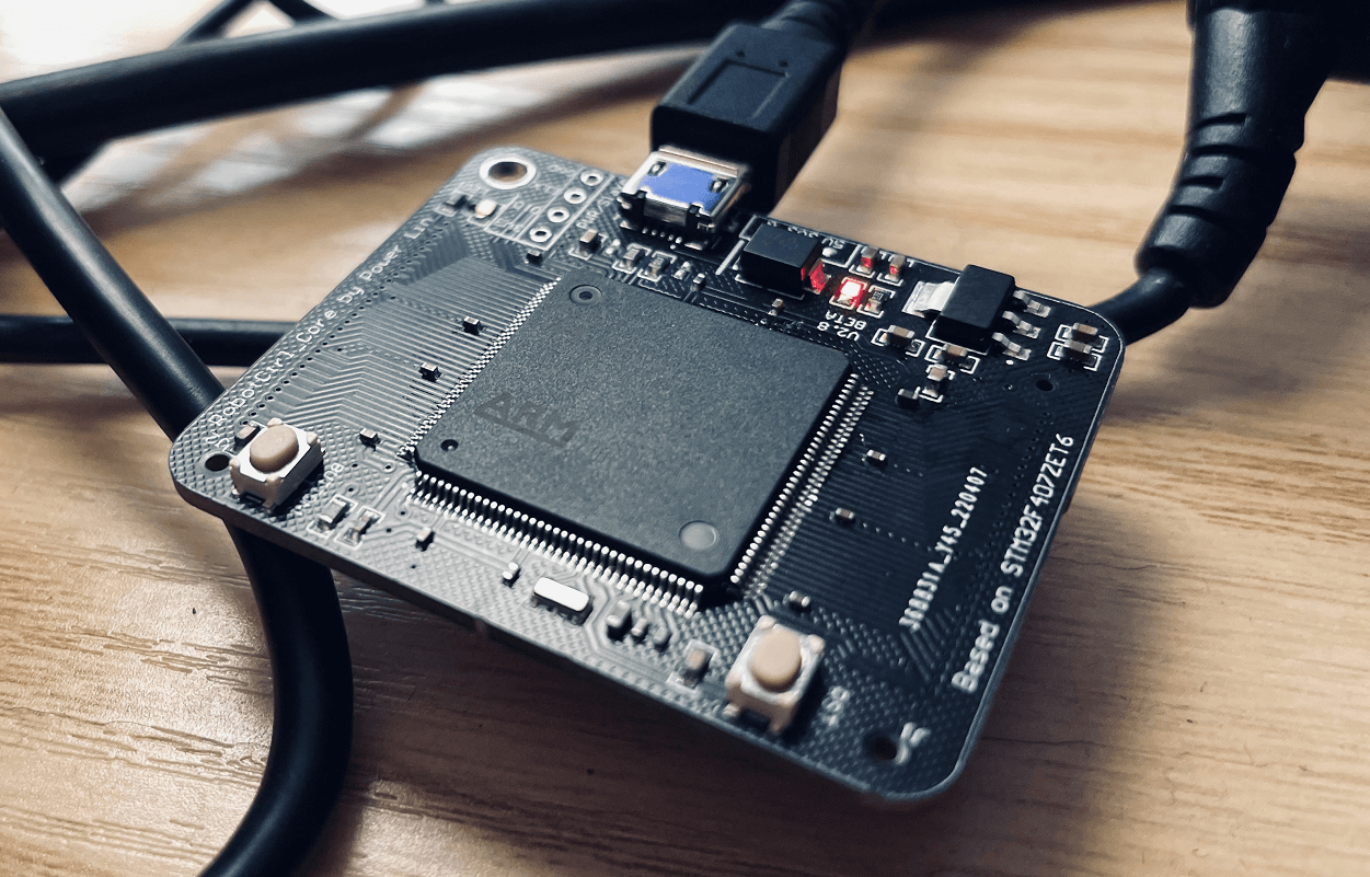
RobotCtrl_Core - Core Board
Project Repository: linyuxuanlin/RobotCtrl/RobotCtrl_Core
Project Online Preview:
Note: This project is included in RobotCtrl - STM32 Universal Development Kit.
Schematic Design
The primary functions of RobotCtrl_Core are as follows:
- Power supply voltage regulation circuit (5V to 3.3V with test points)
- Microcontroller minimum system
- Power circuit (power decoupling, ADC analog power)
- Reset circuit (external reset button)
- Clock circuit (HSE passive crystal oscillator)
- Download and debug interface (SW)
- Boot mode (select booting from the main flash memory)
- USB power and communication circuit (USB-Micro)
- B2B connectors (access to all IO)
- On-board peripherals
Power Supply Circuit
RobotCtrl_Core can be powered by a 5V input via the USB interface or B2B connector, which is then converted to 3.3V for use by the microcontroller core and on-board peripherals. The voltage regulation circuit uses an LDO (AMS1117-3.3) with a maximum current of 1A and includes a power indicator LED. It also reserves key test points.
The basic principles of the LDO can be found in the article Power Supply Topology - Linear Regulator.
Microcontroller Minimum System
The design of the microcontroller minimum system is divided into several parts: power supply, reset, download and debug, clock, and boot mode. For foundational knowledge, you can refer to the articles How to Design a Minimum System for a Microcontroller and STM32F4 Hardware Development.
Power Circuit
Decoupling Capacitors:
- VDD: A total of 10 μF ceramic capacitor, with an additional 100 nF ceramic capacitor connected to each VDD pin.
- VDDA: 100 nF ceramic capacitor + 1 µF ceramic capacitor.
VCAP Capacitor
- Connect a 2.2 µF ceramic capacitor to ground for each.
Reset Circuit
The power monitor is enabled, i.e., PDR_ON is pulled up through a 120Ω resistor. Additionally, a reset button with hardware debouncing is also added.
Clock Circuit
An external high-speed clock (HSE) uses a 8M passive crystal oscillator from Murata.
Download and Debug Interface
This design directly exposes the download and debug interface without the need for external pull-up/pull-down resistors (because STM32 has integrated them internally).
Boot Mode
Select booting from the main flash memory, i.e., BOOT0 is connected to a 10 K pull-down resistor, while BOOT1 can be set as desired.
USB Power and Communication Circuit (USB-Micro)
The STM32 microcontroller comes equipped with built-in USB peripherals, making it easy to establish USB communication by directly connecting the interface (on the STM32F07ZE chip, this is achieved through the PA11 and PA12 pins).
The USB interface also supports external power supply (VUSB).
B2B Connectors
The B2B connectors selected are from the 3710 series by DFRobot. The RobotCtrl_Core board uses a pair of 3710M060037G3FT01 (male connectors), while the RobotCtrl_Func expansion board uses a pair of F060037G0FR01 (female connectors) for compatibility. One pair of B2B connectors (totaling 120 pins) is sufficient to fully utilize all the I/O pins of the STM32F407ZE, maximizing the utilization of system resources.
For more information on the B2B connectors, please refer to the 3710F Connector Data.
User Buttons and LEDs
To facilitate simple verification and debugging, the RobotCtrl_Core board is equipped with a user button and a user LED. The button is configured in GPIO input mode with internal pull-up and an additional MLCC capacitor for hardware debouncing. The LED is configured in GPIO output mode, and it is turned on by setting the pin to a high level. There is also a resistor in series with the LED to limit current.
For specific pin configurations, please refer to the schematic diagram.
Hardware Testing
Power testing involves connecting the USB socket to a 5V power source (or using an external expansion board via the B2B connectors) and measuring the corresponding voltage at the 3.3V test point. In actual testing, the voltage measures 3.32V, which confirms successful testing.
Function testing includes programming the initial program (which allows the user button to control the user LED) and testing power-on, program burning, reset button, user button, power LED, user LED, and USB functionality. During the practical tests, the initial program can be successfully burned into the microcontroller core board using an ST-Link. The reset button can reset the system correctly. In the test program, the user button can turn the user LED on and off. Upon powering up, the power LED lights up as expected. USB functionality is tested using a program for a USB virtual serial port. Opening a serial port tool (with any baud rate) and sending arbitrary characters will result in receiving the same characters, confirming successful testing.
References and Acknowledgments
- Explanation of STM32's PDR_ON Pin (Repost + Supplement)
- DFRobot's 56th Chapter - STM32-F407 Explorer USB Card Reader (Slave) Experiment
Original: https://wiki-power.com/ This post is protected by CC BY-NC-SA 4.0 agreement, should be reproduced with attribution.
This post is translated using ChatGPT, please feedback if any omissions.