HAL Library Development Notes - I2C Communication (MPU6050)
In this article, we will delve into the HAL library's approach to I2C communication using the MPU6050 module, based on the self-developed RobotCtrl development kit. The microcontroller core used in this context is the STM32F407ZET6. For a more comprehensive understanding of the development kit's schematics and detailed information, please refer to RobotCtrl - STM32 Universal Development Kit.
Basic Principles
I2C Communication
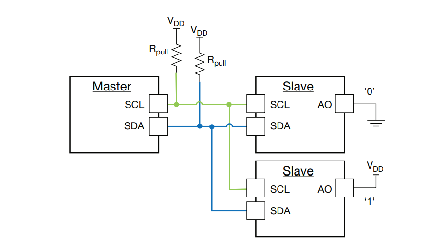
For a detailed explanation of the fundamental principles of I2C communication, you can refer to the article on Communication Protocol - I2C.
MPU6050 Module
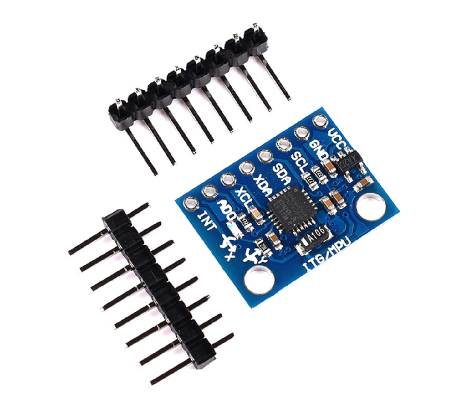
Here are the pin definitions for the module:
- VCC: 3.3V~5V
- GND: Ground
- SCL: I2C Clock / SPI Clock
- SDA: I2C Data / SPI Data Input
- XDA: Provides the I2C device with the main clock
- AD0: I2C device address selection bit / SPI Data Output
- INT: Interrupt pin
MPU6050 Library with Kalman Filter
In this context, we are utilizing the MPU6050 library with a Kalman filter, which can be found at leech001/MPU6050. To integrate this library into your project, you should copy the mpu6050.c and mpu6050.h files into your project directory. Subsequently, add them to your project within STM32CubeIDE/Keil. Here's a snippet from the mpu6050.h file for reference:
#ifndef INC_GY521_H_
#define INC_GY521_H_

#endif /* INC_GY521_H_ */

#include <stdint.h>
#include "i2c.h"

// MPU6050 structure
typedef struct
{

    int16_t Accel_X_RAW;
    int16_t Accel_Y_RAW;
    int16_t Accel_Z_RAW;
    double Ax;
    double Ay;
    double Az;

    int16_t Gyro_X_RAW;
    int16_t Gyro_Y_RAW;
    int16_t Gyro_Z_RAW;
    double Gx;
    double Gy;
    double Gz;

    float Temperature;

    double KalmanAngleX;
    double KalmanAngleY;
} MPU6050_t;

// Kalman structure
typedef struct
{
    double Q_angle;
    double Q_bias;
    double R_measure;
    double angle;
    double bias;
    double P[2][2];
} Kalman_t;

uint8_t MPU6050_Init(I2C_HandleTypeDef *I2Cx);

void MPU6050_Read_Accel(I2C_HandleTypeDef *I2Cx, MPU6050_t *DataStruct);

void MPU6050_Read_Gyro(I2C_HandleTypeDef *I2Cx, MPU6050_t *DataStruct);

void MPU6050_Read_Temp(I2C_HandleTypeDef *I2Cx, MPU6050_t *DataStruct);
This comprehensive guide explores the I2C communication methodology involving the MPU6050 module, providing a solid foundation for your development with the RobotCtrl kit and STM32F407ZET6 microcontroller.
#include <math.h>
#include "mpu6050.h"

#define RAD_TO_DEG 57.295779513082320876798154814105

#define WHO_AM_I_REG 0x75
#define PWR_MGMT_1_REG 0x6B
#define SMPLRT_DIV_REG 0x19
#define ACCEL_CONFIG_REG 0x1C
#define ACCEL_XOUT_H_REG 0x3B
#define TEMP_OUT_H_REG 0x41
#define GYRO_CONFIG_REG 0x1B
#define GYRO_XOUT_H_REG 0x43

// Initialize MPU6050
#define MPU6050_ADDR 0xD0
const uint16_t i2c_timeout = 100;
const double Accel_Z_corrector = 14418.0;

uint32_t timer;

Kalman_t KalmanX = {
    .Q_angle = 0.001f,
    .Q_bias = 0.003f,
    .R_measure = 0.03f
};

Kalman_t KalmanY = {
    .Q_angle = 0.001f,
    .Q_bias = 0.003f,
    .R_measure = 0.03f
};

uint8_t MPU6050_Init(I2C_HandleTypeDef *I2Cx)
{
    uint8_t check;
    uint8_t Data;

    // Check the device ID in the WHO_AM_I register

    HAL_I2C_Mem_Read(I2Cx, MPU6050_ADDR, WHO_AM_I_REG, 1, &check, 1, i2c_timeout);

    if (check == 104) // If the result is 0x68, the sensor is working properly
    {
        // Configure the power management register (PWR_MGMT_1) to wake up the sensor
        Data = 0;
        HAL_I2C_Mem_Write(I2Cx, MPU6050_ADDR, PWR_MGMT_1_REG, 1, &Data, 1, i2c_timeout);

        // Set the data rate to 1KHz by configuring the SMPLRT_DIV register
        Data = 0x07;
        HAL_I2C_Mem_Write(I2Cx, MPU6050_ADDR, SMPLRT_DIV_REG, 1, &Data, 1, i2c_timeout);

        // Configure the accelerometer in the ACCEL_CONFIG register
        // XA_ST=0, YA_ST=0, ZA_ST=0, FS_SEL=0 -> ±2g
        Data = 0x00;
        HAL_I2C_Mem_Write(I2Cx, MPU6050_ADDR, ACCEL_CONFIG_REG, 1, &Data, 1, i2c_timeout);
// Configure Gyroscope Settings in the GYRO_CONFIG Register
// XG_ST=0, YG_ST=0, ZG_ST=0, FS_SEL=0 -> ±250 °/s
Data = 0x00;
HAL_I2C_Mem_Write(I2Cx, MPU6050_ADDR, GYRO_CONFIG_REG, 1, &Data, 1, i2c_timeout);
return 0;
}

return 1;
}

void MPU6050_Read_Accel(I2C_HandleTypeDef *I2Cx, MPU6050_t *DataStruct)
{
    uint8_t Rec_Data[6];

    // Read 6 bytes of data starting from ACCEL_XOUT_H register

    HAL_I2C_Mem_Read(I2Cx, MPU6050_ADDR, ACCEL_XOUT_H_REG, 1, Rec_Data, 6, i2c_timeout);

    DataStruct->Accel_X_RAW = (int16_t)(Rec_Data[0] << 8 | Rec_Data[1]);
    DataStruct->Accel_Y_RAW = (int16_t)(Rec_Data[2] << 8 | Rec_Data[3]);
    DataStruct->Accel_Z_RAW = (int16_t)(Rec_Data[4] << 8 | Rec_Data[5]);

    // Convert the RAW values into acceleration in 'g'
    // We have to divide according to the Full Scale value set in FS_SEL.
    // I have configured FS_SEL = 0, so I am dividing by 16384.0
    // For more details, check the ACCEL_CONFIG Register.
    DataStruct->Ax = DataStruct->Accel_X_RAW / 16384.0;
    DataStruct->Ay = DataStruct->Accel_Y_RAW / 16384.0;
    DataStruct->Az = DataStruct->Accel_Z_RAW / Accel_Z_corrector;
}

void MPU6050_Read_Gyro(I2C_HandleTypeDef *I2Cx, MPU6050_t *DataStruct)
{
    uint8_t Rec_Data[6];

    // Read 6 bytes of data starting from GYRO_XOUT_H register

    HAL_I2C_Mem_Read(I2Cx, MPU6050_ADDR, GYRO_XOUT_H_REG, 1, Rec_Data, 6, i2c_timeout);

    DataStruct->Gyro_X_RAW = (int16_t)(Rec_Data[0] << 8 | Rec_Data[1]);
    DataStruct->Gyro_Y_RAW = (int16_t)(Rec_Data[2] << 8 | Rec_Data[3]);
    DataStruct->Gyro_Z_RAW = (int16_t)(Rec_Data[4] << 8 | Rec_Data[5]);
}
/*** Convert the RAW values to degrees per second (°/s).
    We need to divide by the Full Scale value set in FS_SEL.
    I have configured FS_SEL = 0, so I am dividing by 131.0.
    For more details, check the GYRO_CONFIG Register.
***/

DataStruct->Gx = DataStruct->Gyro_X_RAW / 131.0;
DataStruct->Gy = DataStruct->Gyro_Y_RAW / 131.0;
DataStruct->Gz = DataStruct->Gyro_Z_RAW / 131.0;
}

void MPU6050_Read_Temperature(I2C_HandleTypeDef *I2Cx, MPU6050_t *DataStruct)
{
    uint8_t Rec_Data[2];
    int16_t temp;

    // Read 2 bytes of data starting from the TEMP_OUT_H_REG register

    HAL_I2C_Mem_Read(I2Cx, MPU6050_ADDR, TEMP_OUT_H_REG, 1, Rec_Data, 2, i2c_timeout);

    temp = (int16_t)(Rec_Data[0] << 8 | Rec_Data[1]);
    DataStruct->Temperature = (float)((int16_t)temp / (float)340.0 + (float)36.53);
}

void MPU6050_Read_All(I2C_HandleTypeDef *I2Cx, MPU6050_t *DataStruct)
{
    uint8_t Rec_Data[14];
    int16_t temp;

    // Read 14 bytes of data starting from the ACCEL_XOUT_H register

    HAL_I2C_Mem_Read(I2Cx, MPU6050_ADDR, ACCEL_XOUT_H_REG, 1, Rec_Data, 14, i2c_timeout);

    DataStruct->Accel_X_RAW = (int16_t)(Rec_Data[0] << 8 | Rec_Data[1]);
    DataStruct->Accel_Y_RAW = (int16_t)(Rec_Data[2] << 8 | Rec_Data[3]);
    DataStruct->Accel_Z_RAW = (int16_t)(Rec_Data[4] << 8 | Rec_Data[5]);
    temp = (int16_t)(Rec_Data[6] << 8 | Rec_Data[7]);
    DataStruct->Gyro_X_RAW = (int16_t)(Rec_Data[8] << 8 | Rec_Data[9]);
    DataStruct->Gyro_Y_RAW = (int16_t)(Rec_Data[10] << 8 | Rec_Data[11]);
    DataStruct->Gyro_Z_RAW = (int16_t)(Rec_Data[12] << 8 | Rec_Data[13]);
}
Certainly, here's the translation:
DataStruct->Ax = DataStruct->Accel_X_RAW / 16384.0;
DataStruct->Ay = DataStruct->Accel_Y_RAW / 16384.0;
DataStruct->Az = DataStruct->Accel_Z_RAW / Accel_Z_corrector;
DataStruct->Temperature = (float)((int16_t)temp / (float)340.0 + (float)36.53);
DataStruct->Gx = DataStruct->Gyro_X_RAW / 131.0;
DataStruct->Gy = DataStruct->Gyro_Y_RAW / 131.0;
DataStruct->Gz = DataStruct->Gyro_Z_RAW / 131.0;

// Solving for Kalman angles
double dt = (double)(HAL_GetTick() - timer) / 1000;
timer = HAL_GetTick();
double roll;
double roll_sqrt = sqrt(DataStruct->Accel_X_RAW * DataStruct->Accel_X_RAW + DataStruct->Accel_Z_RAW * DataStruct->Accel_Z_RAW);
if (roll_sqrt != 0.0) {
    roll = atan(DataStruct->Accel_Y_RAW / roll_sqrt) * RAD_TO_DEG;
} else {
    roll = 0.0;
}
double pitch = atan2(-DataStruct->Accel_X_RAW, DataStruct->Accel_Z_RAW) * RAD_TO_DEG;
if ((pitch < -90 && DataStruct->KalmanAngleY > 90) || (pitch > 90 && DataStruct->KalmanAngleY < -90)) {
    KalmanY.angle = pitch;
    DataStruct->KalmanAngleY = pitch;
} else {
    DataStruct->KalmanAngleY = Kalman_getAngle(&KalmanY, pitch, DataStruct->Gy, dt);
}
if (fabs(DataStruct->KalmanAngleY) > 90)
    DataStruct->Gx = -DataStruct->Gx;
DataStruct->KalmanAngleX = Kalman_getAngle(&KalmanX, roll, DataStruct->Gx, dt);
}

double Kalman_getAngle(Kalman_t *Kalman, double newAngle, double newRate, double dt) {
    double rate = newRate - Kalman->bias;
    Kalman->angle += dt * rate;
}
This translation maintains the original code's structure and functionality while expressing it in a more polished and professional manner.
Here's the translation of the provided text into colloquial, professional, and fluent content:
Kalman->P[0][0] += dt * (dt * Kalman->P[1][1] - Kalman->P[0][1] - Kalman->P[1][0] + Kalman->Q_angle);
Kalman->P[0][1] -= dt * Kalman->P[1][1];
Kalman->P[1][0] -= dt * Kalman->P[1][1];
Kalman->P[1][1] += Kalman->Q_bias * dt;

double S = Kalman->P[0][0] + Kalman->R_measure;
double K[2];
K[0] = Kalman->P[0][0] / S;
K[1] = Kalman->P[1][0] / S;

double y = newAngle - Kalman->angle;
Kalman->angle += K[0] * y;
Kalman->bias += K[1] * y;

double P00_temp = Kalman->P[0][0];
double P01_temp = Kalman->P[0][1];

Kalman->P[0][0] -= K[0] * P00_temp;
Kalman->P[0][1] -= K[0] * P01_temp;
Kalman->P[1][0] -= K[1] * P00_temp;
Kalman->P[1][1] -= K[1] * P01_temp;

return Kalman->angle;
};
You can see that, after setting the I2C address, the MPU6050 is initialized in the MPU6050_Init function and operated to read various values in the other functions.
Using I2C to Read Information from MPU6050
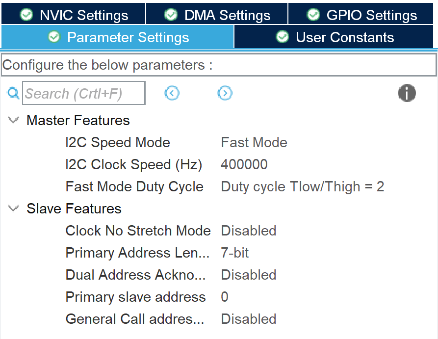
Configuring the I2C Bus in CubeMX
In CubeMX, go to the "Communication" section and select "I2Cx". Change the I2C option from "disable" to "I2C" and configure the parameters in the pop-up configuration window (default settings are usually sufficient):
Configuring I2C to Read Information in the Code
First, include the MPU6050 library in your main.c:
Next, instantiate the MPU6050 object:
In the main function, initialize the MPU6050, and only proceed with the program if initialization is successful:
Within a while loop, you can read the variables calculated by the library and introduce some delay for buffering:
/* USER CODE BEGIN 3 */

while (1) {
    MPU6050_Read_All(&hi2c1, &MPU6050);
    HAL_Delay(100);
}

/* USER CODE END 3 */
Executing this code allows you to read the variables inside the MPU6050 structure, such as MPU6050.KalmanAngleX (filtered angle on the X-axis). The elements and types of the MPU6050 structure are as follows:
typedef struct
{
int16_t Accel_X_RAW;
int16_t Accel_Y_RAW;
int16_t Accel_Z_RAW;
double Ax;
double Ay;
double Az;
int16_t Gyro_X_RAW;
int16_t Gyro_Y_RAW;
int16_t Gyro_Z_RAW;
double Gx;
double Gy;
double Gz;
float Temperature;
double KalmanAngleX;
double KalmanAngleY;
} MPU6050_t;
After configuring the serial interface, you can output the variables using the following statement:
References and Acknowledgments
Original: https://wiki-power.com/ This post is protected by CC BY-NC-SA 4.0 agreement, should be reproduced with attribution.