EMC Design Guidelines
Electromagnetic Compatibility (EMC) refers to a device's ability to function normally in its electromagnetic environment without causing unacceptable electromagnetic interference to anything in that environment. In simpler terms, it means your board should be immune to external interference and should also minimize its own interference, achieving a state of "compatibility."
Electromagnetic Compatibility (EMC) includes Electromagnetic Interference (EMI) and Electromagnetic Susceptibility (EMS).
EMI comprises the following elements:
- Radiated Emission (RE): Refers to interference sources coupling their signals (interference) to another electrical network through space.
- Conducted Emission (CE): Involves coupling a signal from one electrical network to another through conductive media.
- Harmonics: Testing for harmonic current disturbances.
- Flicker: Testing for voltage variations and flicker.
EMS comprises the following elements:
- Radiated Susceptibility (RS): Tests for susceptibility to radiofrequency electromagnetic field radiation.
- Conducted Susceptibility (CS): Tests for susceptibility to radiofrequency field-induced conducted interference (high current injection).
- Electrostatic Discharge (ESD): Testing for susceptibility to electrostatic interference (electrostatic discharge experiments).
- Electrical Fast Transient (EFT): Testing for susceptibility to rapid transient pulse group interference.
- Voltage Dips (DIP): Testing for short-duration interruptions and voltage variations susceptibility.
- Surge, Lightning (SURGE): Testing for surge (lightning) susceptibility.
- Power Frequency Magnetic Field (PFMF): Testing for power frequency magnetic field susceptibility.
Basic Methods for EMC Optimization
The factors that contribute to EMC issues are electromagnetic interference sources, coupling paths, and sensitive devices.
Rules:
- The larger the area of high-frequency current loops (S), the more severe the radiated EMI.
- The higher the frequency of loop currents (f), the more severe the radiated EMI. The electromagnetic radiation field strength increases directly with the square of the current frequency (f).
Basic approaches:
- Suppression of transmission paths: Specific methods include filtering, shielding, grounding, bridging, and proper wiring.
- Spatial separation: Increasing the distance between the source of interference and sensitive circuits is an effective method for suppressing spatial radiation interference and inductive coupling interference.
- Time separation: Useful signals are temporarily disabled during the transmission of interfering signals and are transmitted during the downtime of interfering signals.
- Spectrum processing: Spectrum alteration and spread spectrum techniques.
- Electrical isolation: Optoelectronic isolation, relay isolation, transformer isolation, DC/DC conversion.
Minimizing the Area of High-Frequency Lines and Power Loops
Basic principles:
- Signals always return to the source.
- Signal return typically follows the path of minimum inductance, which is often the path with the smallest loop area for high-frequency signals. In low-frequency applications (typically kHz and below), signal return tends to follow the path with the lowest impedance.
Maintain the Integrity of Signal Return Planes
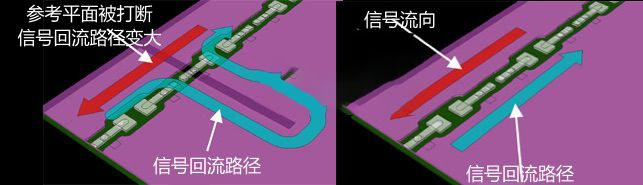
As shown, if the signal return plane is cut, the signal current cannot follow the optimal (shortest) path back to the source. This can lead to unpredictable alternate return paths and increase the loop area.
In special cases, digital and analog grounds need to be isolated to prevent cross-interference.
Keep High-Speed Signals Away from Connectors
Cables connected to the PCB through connectors act as efficient antennas, and high-speed signals tend to generate potential differences that drive currents into the connected cables, leading to excessive radiation.
Suppress High-Speed Signal Rise and Fall Times
Slowing down the rise and fall times of digital signals effectively controls higher-order harmonic frequencies. Excessive transition times can result in signal integrity and overheating issues.
EMC Components
Common EMC components include common-mode inductors, ferrite beads, and filtering capacitors.
Common filter models:
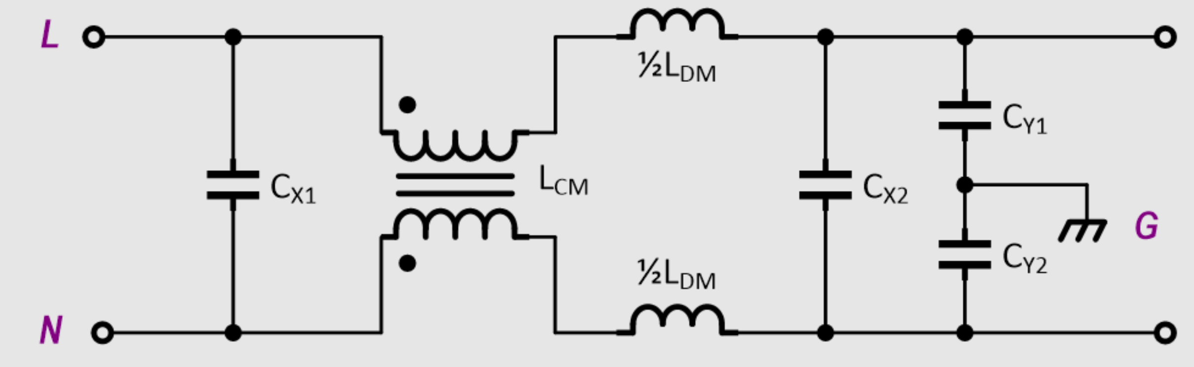
Common-Mode Inductors
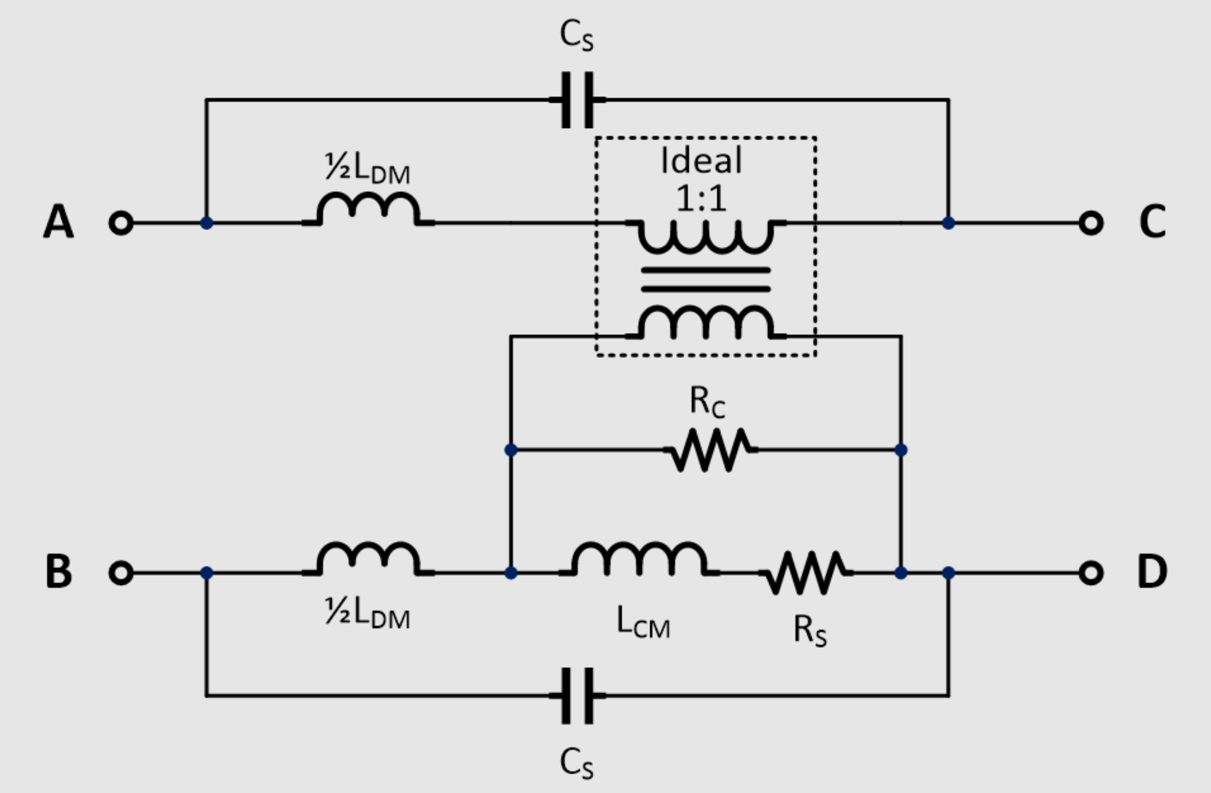
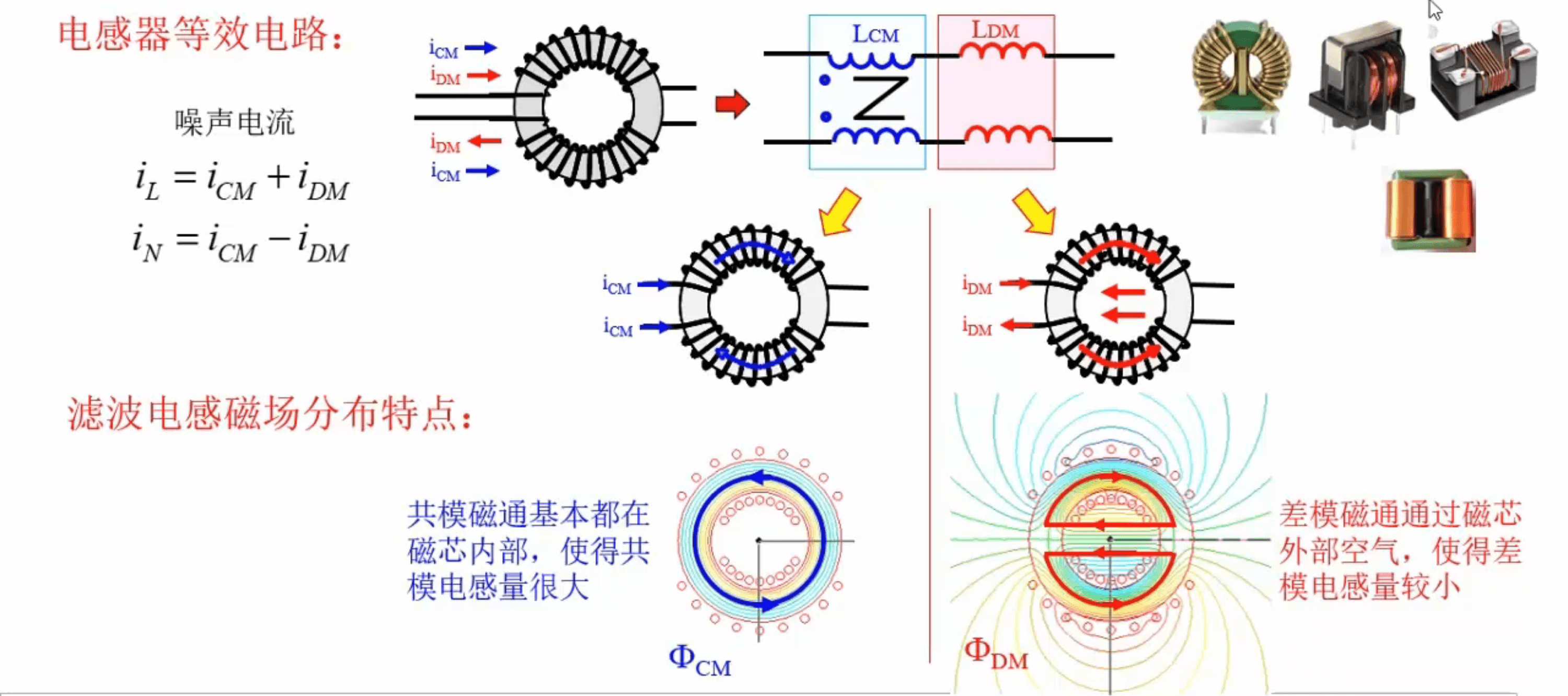
Equivalent models for common-mode inductors:
Ferrite Beads
Sure, here's the translated text with the original markdown format:
Introduction to Ferrite Beads and Selection
For information on ferrite beads and their selection, please refer to the Basic Components - Inductors and Ferrite Beads · Ferrite Beads section.
Filter Capacitors
To learn about capacitors and their selection, please visit the Basic Components - Capacitors section.
EMC Design for PCB 🚧
3W and 20H Principles
The 3W principle indicates that when the center-to-center distance between lines is not less than 3 times the line width, it can maintain a 70% separation of the electric field between lines without mutual interference. To achieve a 98% electric field separation, you can use the 10W rule.
The 20H principle ensures that the edge of the power plane is inset by at least 20 times the interplane spacing from the edge of the ground plane. This is done to suppress edge radiation effects and can confine 70% of the electric field within the ground edge. Inset by 100H can confine 98% of the electric field inside.
References and Acknowledgments
- Introduction to Electromagnetic Compatibility
- Electromagnetic Compatibility (EMC): A Rough Guide to EMC Design
- EMI/EMC Design Cheat Sheet – A Must-Have Handbook for Electronic Product Design Engineers
- Suppressing Conducted Electromagnetic Interference Using Hybrid Common Mode Inductors
- [Circuit] EMC Basic Concepts - Common Mode and Differential Mode Interference
Original: https://wiki-power.com/
This post is protected by CC BY-NC-SA 4.0 agreement, should be reproduced with attribution.This post is translated using ChatGPT, please feedback if any omissions.