AD Basic Operations - Multi-Board System Design 🚧
The reason for using multi-board system design is that a hardware project may include multiple PCBs and various assembly elements such as enclosures. If we design from the perspective of each individual board, the final product may suffer from fitting errors or interference. When designing hardware projects with multiple components, it's best to use mechatronic coordination. Hardware engineers can achieve this directly in Altium Designer without the need for software like SolidWorks.
Creating a Multi-Board Project
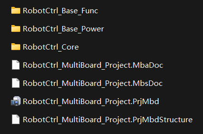
First, create a new project type file (.PrjMbd). Within the project, create logic design files based on the schematic (.MbsDoc) and PCB-based files (.MbaDoc). Then, save your project. At the file system level, copy multiple individual PCB project folders to the same directory as .PrjMbd, as shown below:
Inputting Logic Design
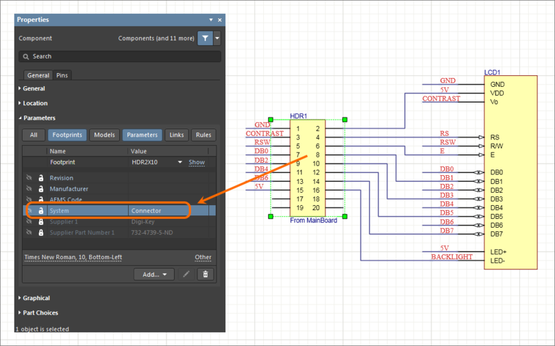
Inputting the logic design is done based on the physical connectors on the PCB. Before this, you need to add parameters to the connectors in the project's schematic (open the connector's properties and add Parameters with the name System and the value Connector).
Creating Modules and Linking Projects
In the logic design file (.MbsDoc), place modules and double-click on them to open their properties. Select the corresponding source PCB project.
Importing Interface Data from Sub-Projects
Right-click and select Design - Import from Sub-Project to automatically import ports with parameters set as connectors.
Adding Logic Connections Between Modules
Use the shortcut P - W to draw connection lines. Click on a connection line to modify the detailed port connections for two modules in the properties panel. If a connector needs to connect to multiple boards, you can split a port within the properties.
Physical Multi-Board Assembly
Importing PCBs from Logic Design Files
Use the shortcut D - I to import the PCBs corresponding to the logic design file.
Simulate Assembly
Drag the coordinate axes of each PCB to simulate the assembly.
Generating Production Data
🚧
References and Acknowledgments
- What is the Experience of Multi-Board Design in PCB?
- Capturing the Logical System Design
- Creating the Physical Multi-Board Assembly
- Generating Production Data for Multi-Board Design
Original: https://wiki-power.com/ This post is protected by CC BY-NC-SA 4.0 agreement, should be reproduced with attribution.
This post is translated using ChatGPT, please feedback if any omissions.