Communication Protocol - SPI
SPI (Serial Peripheral Interface) is a full-duplex, synchronous, serial, master-slave, bus communication protocol with a data transfer rate of 8 Mbit. SPI can only have one master and can be connected to one or more slaves. When connecting multiple devices, the chip select (CS) pin is used.
SPI Pins
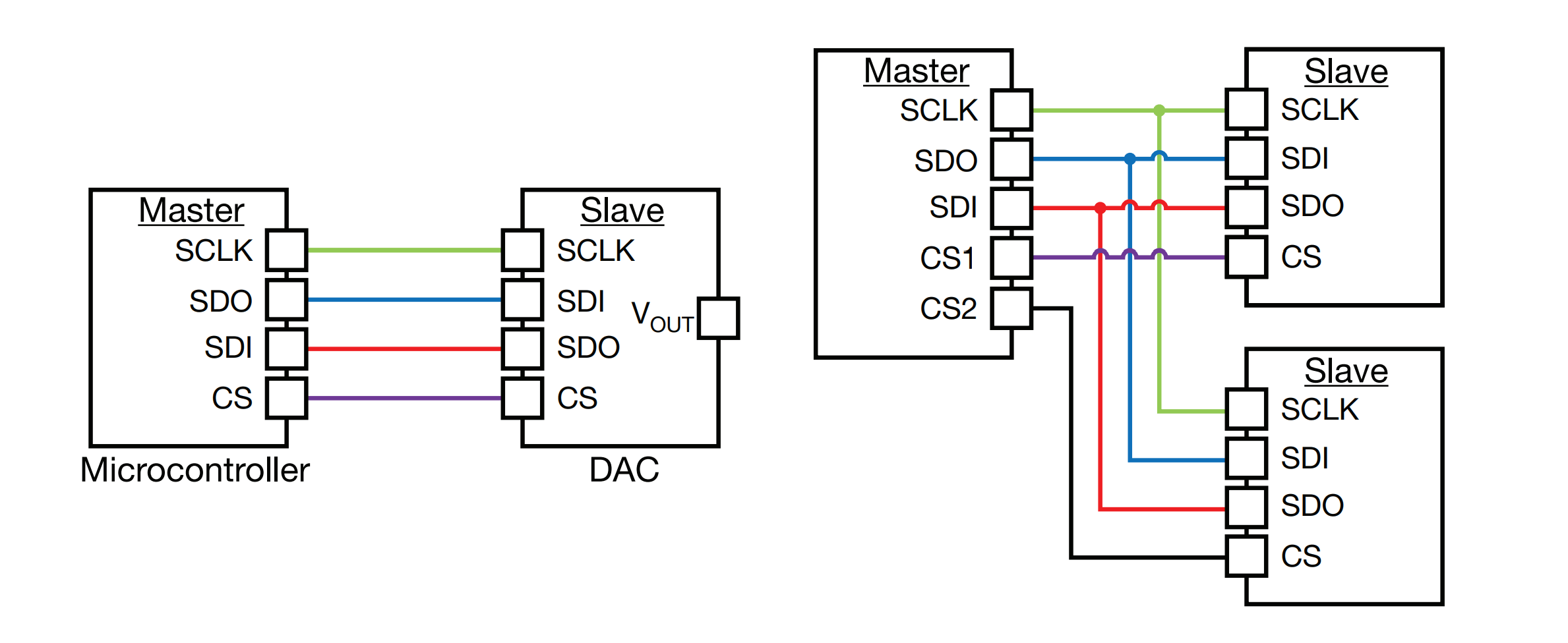
- SCLK (serial clock): A clock signal driven by the master, sampled as input by the slave. The signals on SDO and SDI are latched based on the clock signal on SCLK. One clock cycle transfers 1 bit of data, so the transfer rate is equivalent to the clock frequency generated by the master.
- SDI/SDO (serial data in / serial data out): Describes the direction of the data flow relative to the master, but more often MOSI (Master Out Slave In) and MISO (Master In Slave Out) appear on the board. Correspondingly, SDO is MOSI on the master and MISO on the slave; while SDI is MISO on the master and MOSI on the slave; in a daisy-chain topology, the MISO of device A is connected to the MISO of device B.
- CS/SS (chip select / slave select): Driven by the master, used to arbitrate the priority of communication on the SPI bus. When the CS line is low, SPI communication is activated. CS is active low.
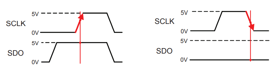
SPI Data Latching
- SPI data is latched on the rising or falling edge of SCLK.
- The edge at which data is latched is called the critical edge.
- For example, the left image below represents latching logic
1on the rising edge of SDO, and the right image represents latching logic0on the falling edge.
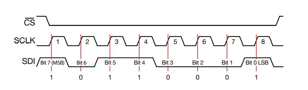
SPI Read Segment Example
- Critical edge is the rising edge.
- Master outputs to the slave (SDI on the slave side).
- CS pin is pulled low to 0V to activate SPI.
- Data is transferred from the most significant bit (MSB) to the least significant bit (LSB) in order on the rising edge of SCLK.
- Transferred data:
1011001
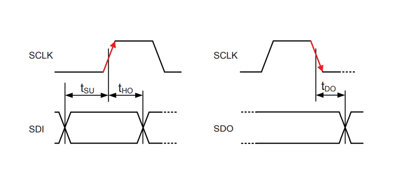
SPI Critical Edge
- \(t_{SU}\) (setup time): Defines how long before the critical edge event, the SDI data should be determined and stabilized.
- \(t_{HO}\) (hold time): Defines how long the data on SDI must be maintained after the critical edge event.
- \(t_{DO}\) (delay time): Defines the delay time of the valid data on SDO after the critical edge event.
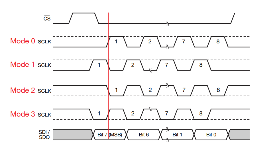
SPI Transfer Modes (4 modes)
- CPOL (clock polarity): The polarity of the clock when idle (not transferring data),
0represents low level,1represents high level. - CPHA (clock phase): Defines whether the latch is performed on the rising or falling edge.
0represents latch on the first changing edge;1represents latch on the second changing edge.
| Mode Number | CPOL (Clock Polarity) | CPHA (Clock Phase) | Latching Edge |
|---|---|---|---|
| 0 | 0 (Low Level) | 0 (Latch on First Edge) | Rising Edge |
| 1 | 0 (Low Level) | 1 (Latch on Second Edge) | Falling Edge |
| 2 | 1 (High Level) | 0 (Latch on First Edge) | Falling Edge |
| 3 | 1 (High Level) | 1 (Latch on Second Edge) | Rising Edge |
Daisy Chain
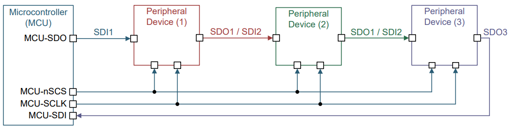
In normal mode, each slave in SPI requires a CS line. When there are multiple slaves, it will occupy too many IO ports on the host. By using the daisy chain topology, only one CS line is needed to drive all the slaves.
The principle of daisy chain is that data is transmitted from the host to the first slave, and then from the first slave to the second slave, and so on. The data is cascaded along the line until it reaches the last slave in the series, and the last slave transfers the data to the host via SDO.
Advantages and Disadvantages of SPI
Advantages:
- Full-duplex communication
- Push-pull drive, providing good signal integrity and high speed
- Flexible protocol, not limited to 8-bit per byte
- Simple hardware design
- No pull-up resistors required, resulting in lower power consumption
- No arbitration mechanism or related failure modes
- Slaves do not need a clock (provided by the host)
- No separate addresses required for the devices
- No transceivers required
- Signals are unidirectional, making it easy to achieve electrical isolation
- Clock speed has no upper limit
Disadvantages:
- Requires more pins compared to I2C
- Slaves cannot perform hardware acknowledgment
- No error checking mechanism, such as parity bit in UART
- Only one master allowed
- Lack of standardization, making it difficult to verify consistency
- Relatively short transmission distance (compared to CAN, RS232, RS485, etc.)
References and Acknowledgements
- "Analog Engineer's Pocket Reference"
Original: https://wiki-power.com/ This post is protected by CC BY-NC-SA 4.0 agreement, should be reproduced with attribution.
This post is translated using ChatGPT, please feedback if any omissions.