Communication Protocol - CAN 🚧
CAN (Controller Area Network) is a serial communication bus with a multi-master architecture. The basic design specifications require high bit rates, high electromagnetic interference resistance, and the ability to detect any errors that occur. Even when the signal transmission distance reaches 10 km, CAN-bus can still provide a data transfer rate of up to 5 Kbps.
CAN Circuit Design
The design of the CAN module is based on the CAN chip, which converts the serial signals (RX/TX) to CAN differential signals (CANH/CANL). Here are two commonly used CAN transceivers.
Based on TJA1050
For complete information, please refer to Modularity_of_Functional_Circuit/Module_Design-CAN_Communication/Based_on_TJA1050
Features
- Power supply: 5V (4.75-5.25V)
- High-speed rates: 60 Kbps-1 Mbps
- Fully compliant with ISO 11898 standard
- Low electromagnetic emission (EME)
- Differential receiver with a wide input range for electromagnetic interference (EMI) immunity
- Can connect at least 110 nodes
- Nodes that are not powered on will not interfere with the bus
Operating Modes
The TJA1050 has two operating modes (High-Speed/Silent) controlled by pin S (RS).
High-Speed Mode:
High-Speed mode is the normal operating mode, and it can be entered by grounding pin S. Since pin S has a built-in pull-down resistor, it defaults to High-Speed mode even if it is not externally connected.
In this mode, the bus output signals have a fixed slope and switch at the fastest speed, making it suitable for maximum bit rates and/or maximum bus length. The transceiver has minimal loop delay in this mode.
Silent Mode:
In Silent mode, the transmitter is disabled and does not respond to the input signal on TXD. The power supply current consumed in this mode is the same as in the Standby mode. Silent mode can be entered by connecting pin S to a high logic level.
In Silent mode, a node can be set to a completely passive state on the bus. The microcontroller no longer directly accesses the CAN controller, and the TJA1050 releases the bus.
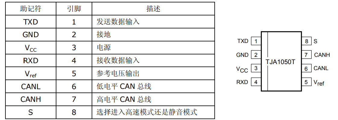
Chip Pins
Reference Circuit
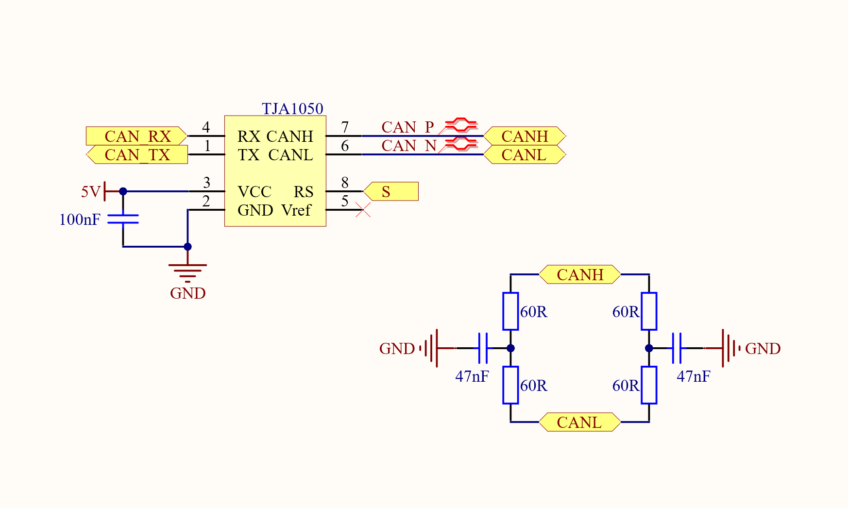
As shown in the diagram, the CAN protocol controller (e.g., microcontroller) is connected to the transceiver via the serial lines (RX/TX). The transceiver converts the signals to CAN signals (CANH/CANL) and the High-Speed/Silent mode is selected using pin S.
Based on SN65HVD230
For complete information, please refer to Modularity_of_Functional_Circuit/Module_Design-CAN_Communication/Based_on_SN65HVD230
Features
- Powered by a single 3.3V supply
- Can connect at least 120 nodes
- Low current standby mode
- Speed: up to 1 Mbps
Operating Modes
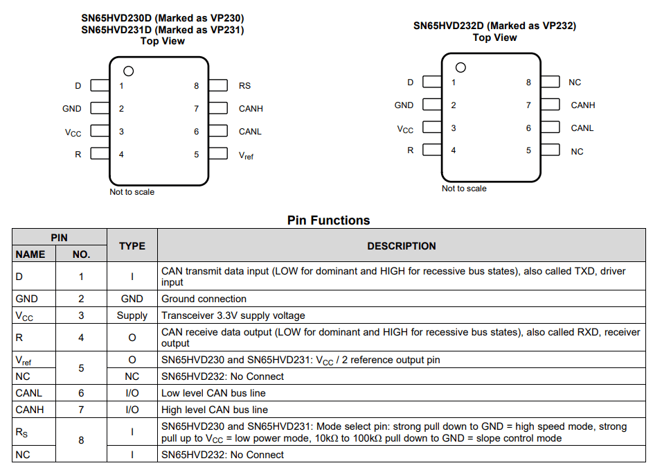
The SN65HVD230 has three operating modes (High-Speed/Slope/Silent) controlled by pin S (RS). Generally, we use the High-Speed mode.
High-Speed Mode:
Pull Rs down to GND to enable High-Speed mode.
Slope Mode:
Pull Rs down to GND using a resistor between 10k and 100k. Please refer to the datasheet for the specific resistor value based on the desired speed.
Low Power Mode:
Pull Rs up to 3.3V.
Chip Pins
Reference Circuit
PESD2CAN is a CAN-specific ESD protection diode that protects the chip from electrostatic discharge and other transient factors.
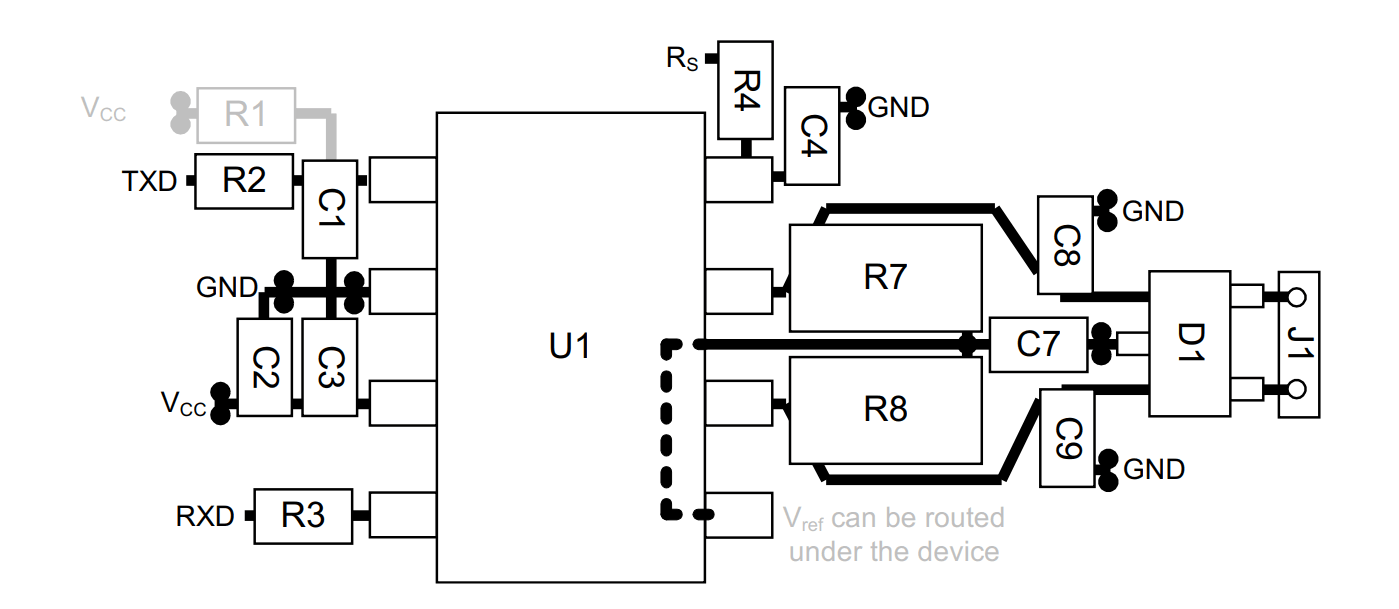
The reference PCB layout is as follows:
Differences between TJA1050 and SN65HVD230
The main difference between TJA1050 and SN65HVD230 is the operating voltage. TJA1050 operates in a 5V environment, while SN65HVD230 operates in a 3.3V environment.
Common considerations:
- When routing the CAN signal lines on the PCB, use differential lines.
- Termination resistors are generally only required at the starting and ending points of the CAN lines, not in the middle.
- If it is necessary to filter and stabilize the common mode voltage of the bus, split termination resistors can also be used (as shown above, divided into two 60Ω resistors with a capacitor connected to ground in the middle).
CAN Interface EMC Design
In CAN communication, cables are prone to coupling external interference, which can affect signal transmission and even impact the internal core sensitive circuits through the interface circuit.
CAN interface protection devices mainly include: filtering capacitors, common mode inductors, coupling capacitors, and TVS diodes.
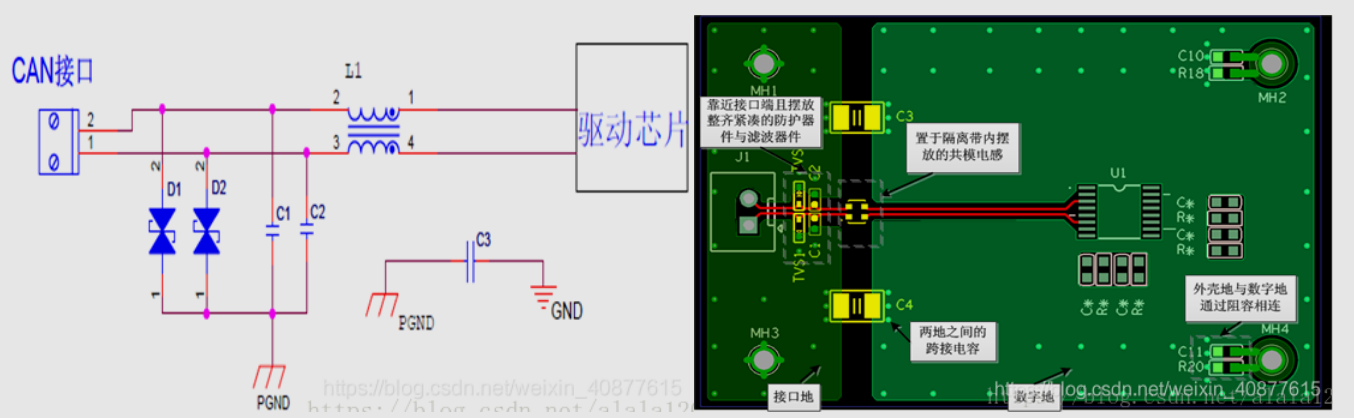
- Filtering capacitors \(C_1, C_2\): Provide a low impedance return path for interference. The selection range is 22pF~1000pF, with a typical value of 100pF.
- Common mode inductor \(L_1\): Used to filter out common mode interference on the differential lines. The impedance selection range is 120Ω/100MHz~2200Ω/100MHz, with a typical value of 600Ω/100MHz.
- Coupling capacitors \(C_3, C_4\): Used for isolation between the interface ground and digital ground, with a typical value of 1000pF/2kV.
- TVS diodes \(D_1, D_2\): Used to protect against ESD or momentary high-energy shocks, clamping the voltage of the circuit within a predetermined range to ensure that subsequent circuit devices are not damaged by transient high-energy shocks.
References and Acknowledgements
Original: https://wiki-power.com/
This post is protected by CC BY-NC-SA 4.0 agreement, should be reproduced with attribution.This post is translated using ChatGPT, please feedback if any omissions.