Communication Protocol - Serial Communication
Serial communication can be considered as the most commonly used and fundamental communication method in microcontrollers. It is commonly used as a means of debugging, communicating with microcontrollers to monitor data and send commands, and can also be used for communication between two microcontrollers. The physical layer of serial communication is RS-232 and TTL standards.
Protocol Layer
Parallel and Serial
- Parallel Communication: Each data bit is transmitted simultaneously, which is fast but occupies more pin resources.
- Serial Communication: Data is transmitted in bit sequence, which occupies fewer pin resources but relatively slower in speed.
Simplex, Half-Duplex, and Full-Duplex
- Simplex: Data is transmitted in only one direction.
- Half-Duplex: Data is allowed to be transmitted in both directions, but at any given time, data can only be transmitted in one direction, similar to switchable simplex communication.
- Full-Duplex: Data is allowed to be transmitted simultaneously in both directions. Therefore, full-duplex communication is a combination of two simplex communication methods, requiring both sending and receiving devices to have independent transmission and reception capabilities.
Synchronous and Asynchronous
- Synchronous Communication: Transmission with clock synchronization signals. For example, SPI, I2C, and other communication interfaces.
- Asynchronous Communication: Transmission without clock synchronization signals. For example, UART, single-wire.
USART and UART
- UART: Universal Asynchronous Receiver/Transmitter
- USART: Universal Synchronous/Asynchronous Receiver/Transmitter
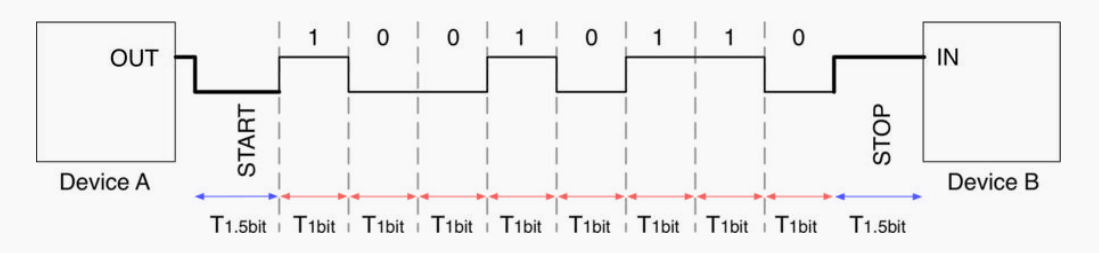
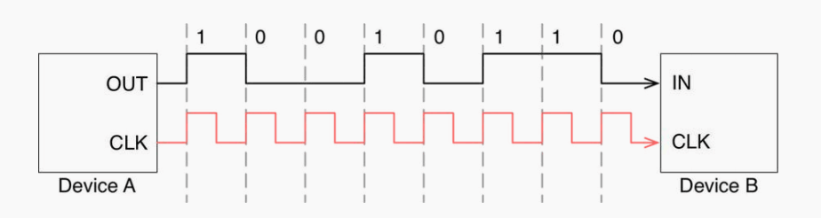
USART is an upgraded version of UART. The difference is that USART has an additional CLK line. When there is no signal on CLK, it indicates that there is no data transmission task. When there is a CLK signal, it means that the signal is being transmitted, and CLK provides clock synchronization function, making the verification more accurate.
Physical Layer
TTL Standard
For TTL standard, please refer to the article TTL Level Interface · Communication Protocol - Digital Logic Level
RS-232 Standard
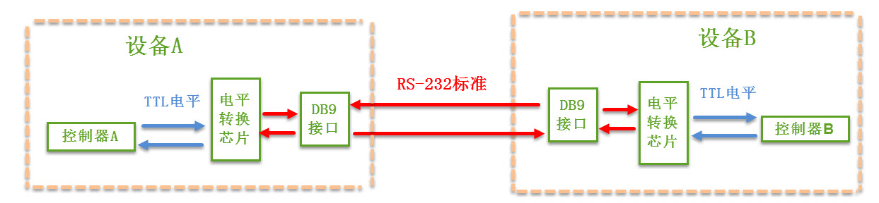
The physical layer of RS-232 communication establishes a connection between the DB9 interfaces of two devices through serial signal lines, and RS-232 voltage levels are used to transmit data signals on the serial signal lines. Since the controller generally uses TTL voltage levels, a dedicated level conversion chip is required to achieve communication.
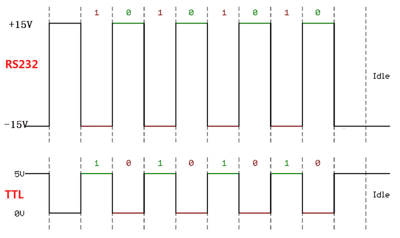
Comparison between TTL and RS-232 voltage levels:
| Communication Standard | Voltage Standard (Transmitter) |
|---|---|
| 5V TTL | Logic 0: 0~0.5V; Logic 1: 2.4V-5V |
| RS-232 | Logic 0: +3V~+15V; Logic 1: -15V~-3V |
Ideal timing diagram in the corresponding state:
RS-232 protocol generally uses DB9 interfaces, with male connectors (pins) commonly used in computers and female connectors (sockets) commonly used in modems:
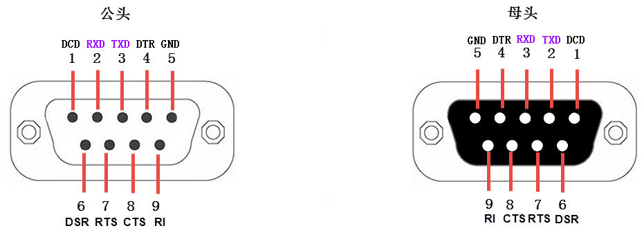
Interface pin definitions:
| Pin Symbol | Name | Description |
|---|---|---|
| DCD | Data Carrier Detect | Data Carrier Detect, used by DTE to inform the other party whether the local machine has received the carrier signal from the other party |
| RXD | Receive Data | Receive Data, the signal for receiving data, i.e., input |
| TXD | Transmit Data | Transmit Data, the signal for transmitting data, i.e., output. The TXD and RXD of two devices should be cross-connected |
| DTR | Data Terminal Ready | Data Terminal Ready, used by DTE to inform the other party whether the local machine is ready |
| GND | Signal Ground | Ground wire, the ground potential between two communication devices may be different, which will affect the level signals of both the transmitter and receiver. Therefore, a ground wire must be used to connect the two serial devices, i.e., common ground |
| DSR | Data Set Ready | Data Set Ready, used by DCE to inform the other party whether the local machine is in a standby state |
| RTS | Request To Send | Request To Send, DTE requests the DCE device to send data to the DCE end |
| CTS | Clear To Send | Clear To Send, DCE responds to the RTS request from the other party, indicating whether the other party can send data |
| RI | Ring Indicator | Ring Indicator, indicating that the DCE end is connected to the line |
The TX/RX of the DB9 male and female connectors are reversed, so they can generally be connected directly. It is equivalent to connecting these signal lines:
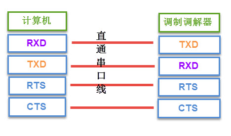
For the RTS, CTS, DSR, DTR, and DCD signals in the serial cable, logic 1 indicates that the signal is valid, and logic 0 indicates that the signal is invalid.
In practical use, sometimes only RXD, TXD, and GND are retained.
References and Acknowledgements
Original: https://wiki-power.com/ This post is protected by CC BY-NC-SA 4.0 agreement, should be reproduced with attribution.
This post is translated using ChatGPT, please feedback if any omissions.