Trigger Modes of an Oscilloscope
The trigger mode of an oscilloscope refers to the action of capturing a waveform only when a preset condition is met. This action of capturing a waveform based on a condition is called triggering.
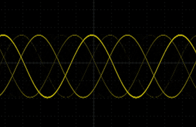
If no trigger is set, the signal captured by the oscilloscope may look like this:
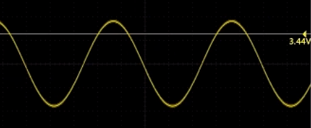
The purpose of triggering is to allow the oscilloscope to display a stable periodic signal:
Three Trigger Modes
Auto Mode
In auto mode, the oscilloscope first triggers according to the trigger condition. If the trigger condition is not met within a set time, the oscilloscope will force a trigger and display the signal.
This mode can be chosen when we are not familiar with the characteristics of a signal. It ensures that the oscilloscope will display a waveform even when other trigger settings are incorrect. Although the waveform may not be stable, it provides us with intuitive judgment for further adjustment of the oscilloscope.
Normal Mode
In normal mode, the oscilloscope only generates a scan when the trigger condition is met (so the trigger mode and level must be set first). If there is no trigger signal, no scan will be performed, and no waveform will be visible on the screen.
The purpose of normal mode is to observe the details of a waveform, especially for complex signals. When we set specific trigger conditions for a particular signal, especially when the time interval that satisfies the trigger condition is relatively long, normal mode can be chosen.
Single Trigger
Single trigger is a subset of normal mode. It also generates a scan only when the trigger condition is met; otherwise, no scan is performed. The difference is that once a scan is completed, even if there are subsequent signals that meet the trigger condition, no further scans will be performed. Another trigger button press is required to initiate a new scan.
Single trigger mode is commonly used to capture signals that occur once or multiple times but do not have periodicity. For example, a power-on signal generated when a circuit is powered on only occurs once. Without using single trigger, it is difficult to capture this signal.
Trigger Types
Slope
The slope trigger options include rising edge, falling edge, and rising and falling edge.
- Rising edge: Set the trigger to occur on the rising edge of the signal.
- Falling edge: Set the trigger to occur on the falling edge of the signal.
- Rising and falling edge: Set the trigger to occur on either the rising or falling edge of the signal.
Coupling
For signals with high noise levels that interfere with accurate triggering, trigger coupling is used to suppress interference and noise in the trigger circuit.
The coupling trigger options include DC, AC, high-frequency reject, low-frequency reject, and noise reject.
- DC: Both the AC and DC components of the trigger source signal are sent to the trigger circuit.
- AC: The DC component of the trigger source signal is filtered out. This is suitable for observing signals ranging from low frequency to higher frequency.
- High-frequency reject: Signals above a specific frequency in the trigger source signal are filtered out. This is suitable for observing signals with high-frequency interference.
- Low-frequency reject: Signals below a specific frequency in the trigger source signal are filtered out. This is suitable for observing signals with low-frequency interference.
- Noise reject: Low-sensitivity DC coupling is used to suppress noise components in the trigger source signal. This is suitable for observing signals with high-frequency noise interference.
References and Acknowledgments
- How Engineers Can Make Good Use of an Oscilloscope? Start with These 3 Aspects...
- Detailed Explanation of Oscilloscope Triggering
Original: https://wiki-power.com/
This post is protected by CC BY-NC-SA 4.0 agreement, should be reproduced with attribution.This post is translated using ChatGPT, please feedback if any omissions.