Design of DC Brushed Motor Drive
Usually, we use PWM to control the H-bridge circuit to achieve control over the direction and speed of the DC brushed motor. The PWM duty cycle is directly proportional to the motor speed.
Basics of H-Bridge
An H-bridge is a bridge circuit that can quickly switch the voltage polarity on a load. This circuit is commonly used to drive DC brushed motors, allowing them to rotate clockwise or counterclockwise. It is called an H-bridge circuit because its structure resembles the letter "H".
An H-bridge consists of four switches. S1 and S3 form the high-side switches of the H-bridge, usually P-type MOSFETs or PNP transistors. S2 and S4 form the low-side switches of the H-bridge, usually N-type MOSFETs or NPN transistors.
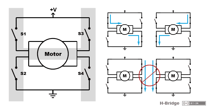
- When switches S1 and S4 are closed and switches S2 and S3 are open, the motor rotates in the normal direction, referred to as the forward direction.
- When switches S2 and S3 are closed and switches S1 and S4 are open, the motor rotates in the reverse direction.
- When switches S1 and S2, or S3 and S4, are closed at the same time, the power supply is short-circuited, posing a risk of damaging the power supply. This is called shoot-through.
- When switches S1 and S3 are closed and switches S2 and S4 are open, or when switches S2 and S4 are closed and switches S1 and S3 are open, the motor does not rotate. At this time, the motor is in a "braking" state, where the counter electromotive force generated by the motor's inertia is short-circuited, creating a counteracting electromotive force that hinders motion, resulting in a "braking" effect.
- When all four switches S1, S2, S3, and S4 are open, the motor is in a freewheeling state and will continue to rotate due to inertia.
In practical circuits, we can use driver chips to precisely control the four MOSFETs in the H-bridge.
Choosing Between Discrete Components and Integrated Chips
Compared to using integrated driver chips, building the circuit with discrete components has lower cost and greater customizability. Generally, when driving a motor, the PWM signal is first output from the MCU, then goes through optocouplers, logic circuits, and finally to the full-bridge/half-bridge MOSFETs.
However, when using discrete components to build a motor drive, there are more considerations, such as dead-time control (to prevent shoot-through), selecting the appropriate driving voltage, designing protection circuits, etc. This increases the complexity of circuit design, increases PCB footprint, raises costs, and introduces design risks.
Usually, when driving a DC brushed motor, we use integrated H-bridge driver chips to control the motor.
Selection of MOSFETs
In motor drive applications, we generally choose enhancement-mode N-MOSFETs. Here are the reasons:
- Choosing enhancement-mode: It can be completely turned off at low levels and fully turned on when the voltage level exceeds the threshold voltage \(U_{GS(TH)}\).
- Choosing N-MOSFETs: P-MOSFETs have fewer options, higher prices, higher on-resistance, resulting in higher heat generation and lower efficiency.
- Choosing MOSFETs: Compared to BJTs, MOSFETs have lower power loss, smaller size, higher driving current, faster response, and lower on-resistance.
In practical designs, to simplify material consolidation, we generally use only N-MOSFETs. However, since N-MOSFETs cannot be directly used for high-side control in an H-bridge (because the conduction condition of N-MOSFETs is \(V_g-V_s>V_{gs(th)}\)), a high-side bootstrap circuit (due to its simple structure) needs to be designed to drive the upper MOSFET. For a detailed introduction to bootstrap circuits, please refer to the article Power Supply Design - Bootstrap Circuit.
Parameters to consider when selecting N-MOSFETs:
- \(V_{DSS}\)
- \(R_{DS(on)}\)
Integrated H-Bridge Driver Chips
H-bridge driver chips generally integrate the following protection circuits:
- Over-voltage protection (OVP)
- Under-voltage lockout (UVLO)
- Over-current protection (OCP)
- Thermal shut-down (TSD)
- Shoot-through protection (STP)
- Electrostatic discharge protection (ESD)
Generally, we use gate driver chips to provide the power supply for the gate of the high-voltage/low-voltage side power N-MOSFET (according to the datasheet, it must be higher than the \(U_{GS(TH)}\) of the MOSFET to turn on the channel between the drain D and the source S). For example, the following figure shows the parameters of the DRV8701 gate driver:
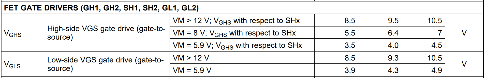
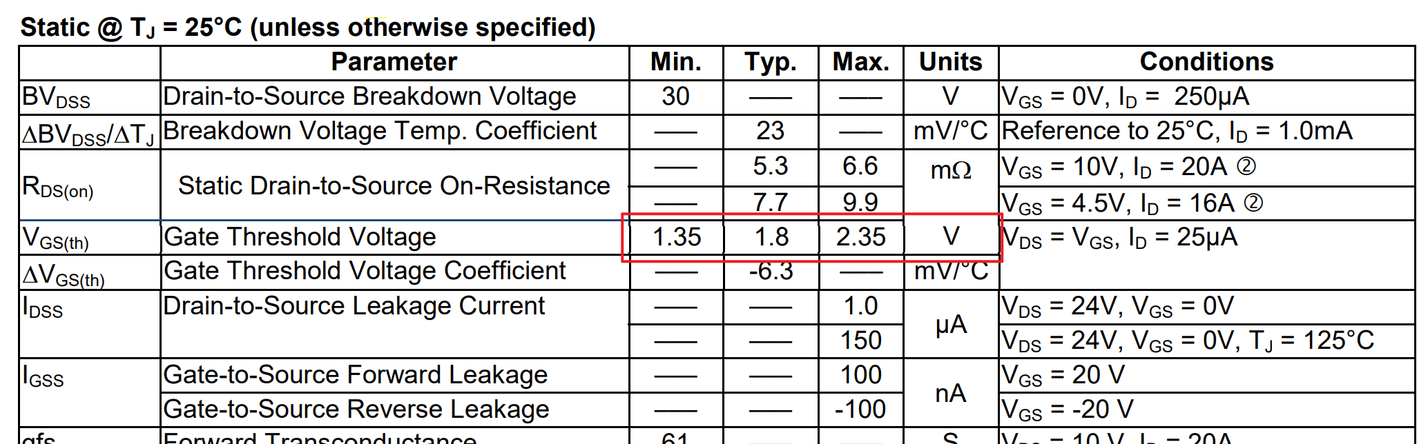
When used with IRFH8330, it can drive this MOSFET:
Selection of PWM Frequency
When using PWM signals to control the motor speed, attention should be paid to the frequency. If the frequency is too low, the motor will generate noise at low speeds, and the response to changes in duty cycle will also be sluggish. On the other hand, if the PWM frequency is too high, it will result in significant switching losses in the H-bridge MOSFETs.
If the datasheet of the H-bridge driver chip does not specify the frequency range, generally speaking, PWM signals with frequencies around 4kHz-200kHz can be used to control the motor speed effectively.
Dead Time Insertion and Cross-Conduction (Shoot-Through) Protection
Dead time can be understood as a delay, which ensures that the upper bridge is completely turned off before the lower bridge is turned on when rotating in the forward direction, and vice versa when rotating in the reverse direction. Too small dead time can be dangerous, while too large dead time can result in poor motor response and low power utilization efficiency.
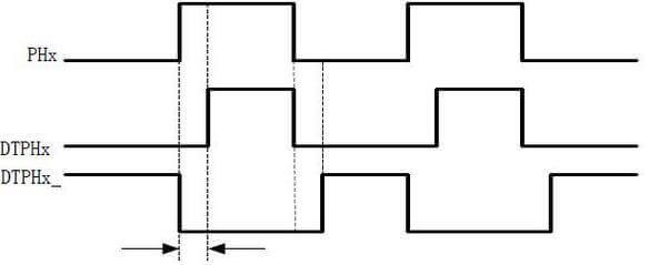
Using an integrated solution: incorporating automatic handshake to utilize the optimal dead time, unaffected by commutation rate, voltage, MOS characteristics, and temperature. The handshake process includes the following steps:
- Receive the signal to disable the high-side MOSFET and monitor \(V_{GS}\) to determine when to disable it.
- Insert dead time and enable the low-side MOSFET.
Decay Modes of the H-Bridge
Decay mode refers to the path through which the motor stops. Since a DC motor is an inductive load (the current in the inductor cannot change abruptly), in order to stop the motor, a freewheeling path needs to be formed to release the energy on the motor, in addition to disconnecting the power supply. Otherwise, the freewheeling current generated by the motor may damage the MOSFETs.
Asynchronous and Synchronous Decay
We can use diodes to construct the freewheeling path, as shown in the figure:
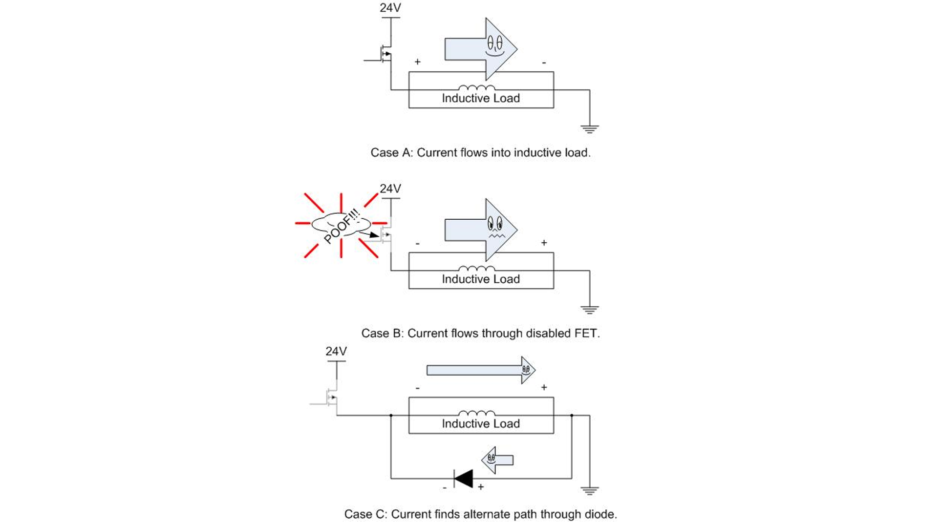
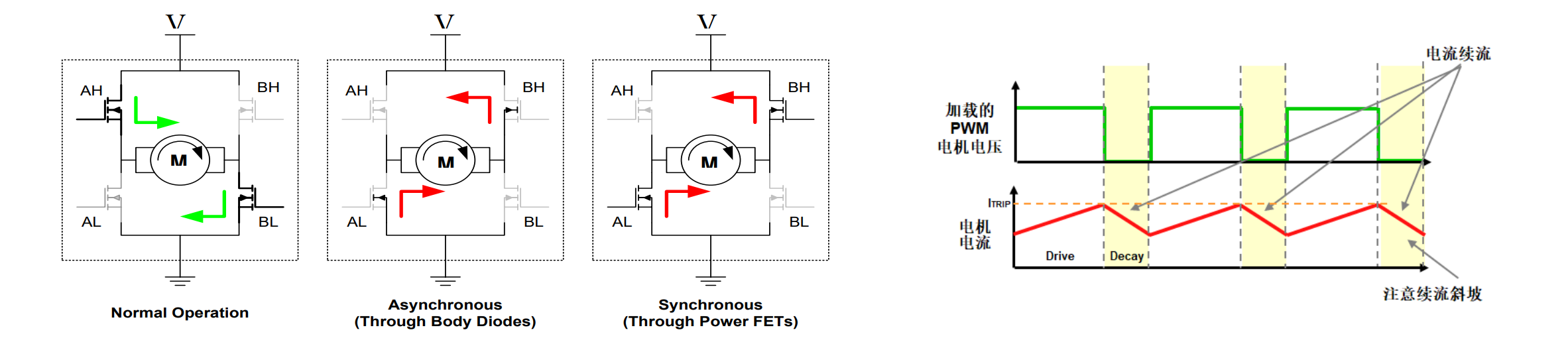
It is known that the body diode inside the MOSFET itself can serve as the freewheeling path. In some applications, a parallel Schottky diode may also be added. Therefore, freewheeling decay can be achieved using the diode, which is called asynchronous decay. However, the losses in asynchronous decay are relatively large (\(2*I*V_D\)). Therefore, another decay method called synchronous decay is introduced. Synchronous decay is achieved by turning on the MOSFET to continue the current flow. Since the on-resistance \(R_{ds(on)}\) of the MOSFET is small, the losses in synchronous decay are relatively small (\(I^2*R_{ds(on)*2}\)). The following mainly explains synchronous decay.
Key Parameters
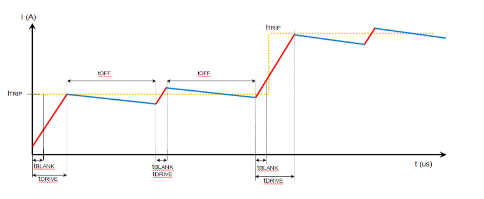
- \(I_{TRIP}\): The current set by the current driver chip, controlled by the driving algorithm.
- \(T_{DRIVE}\): The duration of the driving stage.
- \(T_{BLANK}\): The duration of the dead time stage, to prevent shoot-through.
- \(T_{OFF}\): The duration of the freewheeling stage.
Three Modes of Synchronous Decay
There are three modes of synchronous decay: fast decay, slow decay, and mixed decay. The terms "fast" and "slow" refer to the relative speed of current decay during the freewheeling period, not the motor speed.
The differences between the three modes are:
| Fast Decay | Slow Decay | Mixed Decay | |
|---|---|---|---|
| Phase Current Ripple | Large | Small | Moderate |
| OFF Time \(T_{OFF}\) | Short (may result in higher switch losses) | Long (may hear low frequency noise) | Moderate (balanced frequency and performance) |
| Phase Current Fall Rate | Fast | Slow | Moderate |
| Applicable Range | Suitable for large inductance motors | Suitable for small inductance motors | Moderate |
Fast Decay
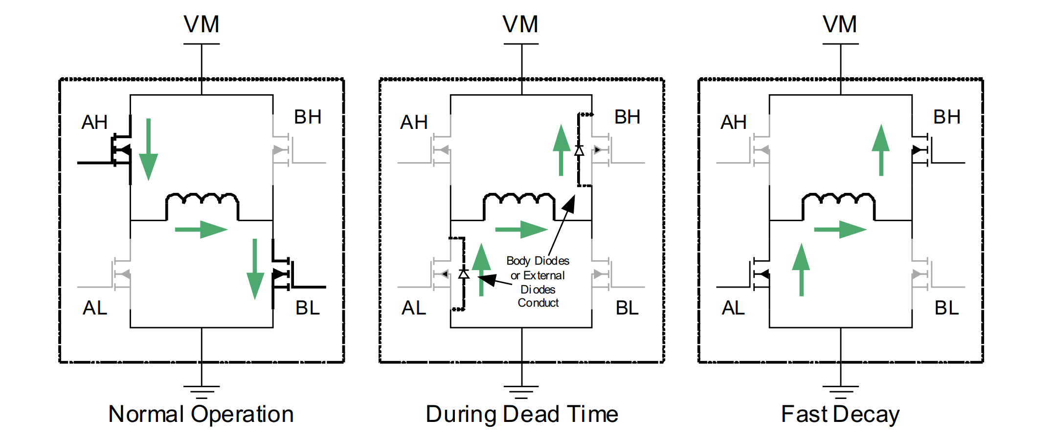
In the process of fast decay, both MOSFETs of the drive are turned off. After the dead time, the two symmetric MOSFETs are turned on to quickly dissipate the current. During the dead time, the H-bridge still undergoes asynchronous decay, but the time is short and can be ignored.
Slow Decay
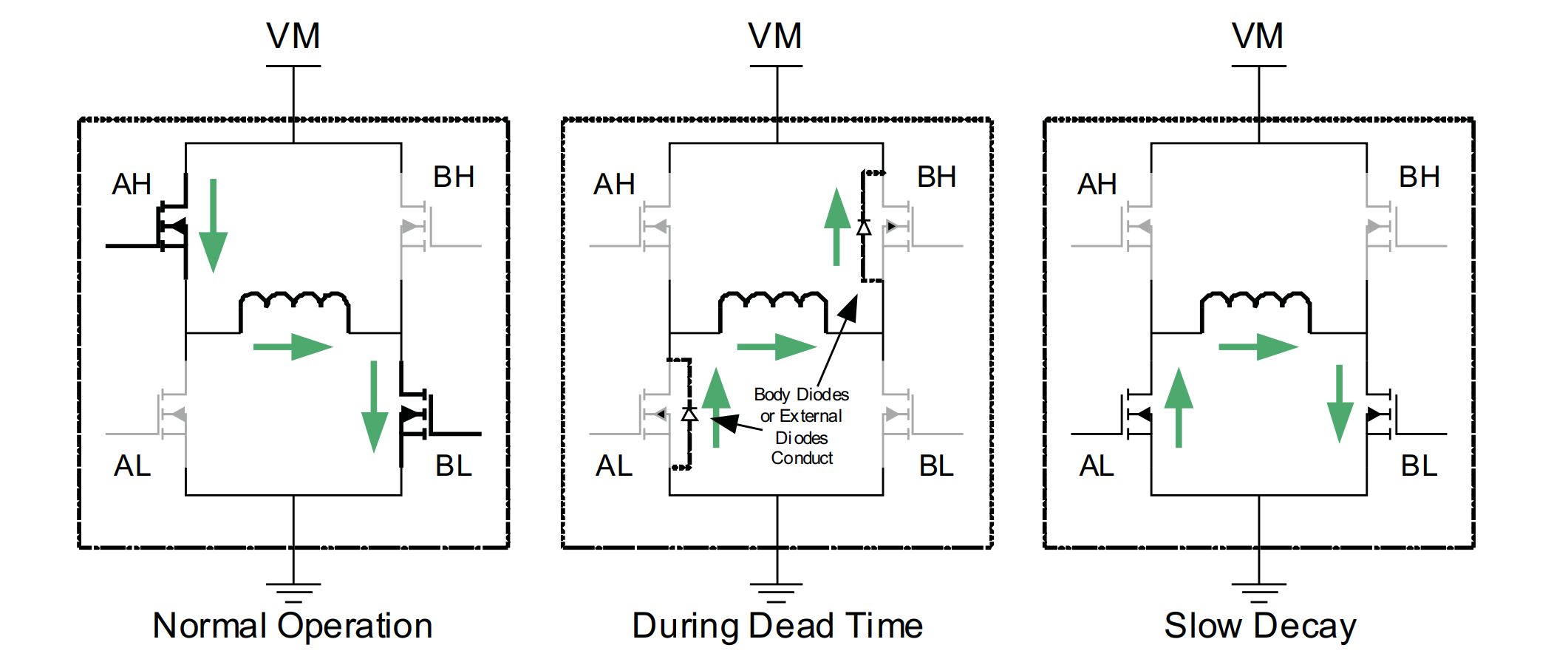
In the process of slow decay, both MOSFETs of the drive are turned off. After the dead time, the two lower MOSFETs are turned on to slowly dissipate the current. Similarly, during the dead time, the H-bridge still undergoes asynchronous decay, but the time is short and can be ignored.
Mixed Decay
In the process of mixed decay, both MOSFETs of the drive are turned off. After the dead time, the two symmetric MOSFETs are turned on for fast decay to quickly dissipate the current. Then the two lower MOSFETs are turned on for slow decay to slowly dissipate the current. The ripple of the phase current in mixed decay mode is between fast decay and slow decay.
EMC Issues and Solutions for Motor Drive
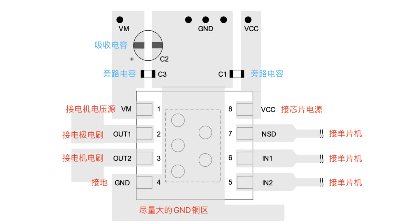
Because DC motors are inductive loads (inductive current cannot change abruptly), in order to prevent unstable rebound or spikes in motor voltage when the H-bridge is turned off, a large capacitor (>100μF, usually an aluminum electrolytic capacitor) can be placed on the motor voltage source to absorb the flywheel current generated during motor braking and stabilize the motor voltage source when the motor switches direction.
Another issue is the parasitic inductance (inductance + resistance) between the motor voltage source and the motor drive board power line, combined with the parasitic capacitance of the PCB, forming an LC resonance tank. When the motor voltage source is supplying power to the motor drive board, if the local bypass capacitance is insufficient, the motor voltage may quickly drop, triggering the parasitic LC and causing oscillation spikes. To reduce the spikes caused by LC resonance in the power line, a 0.1μF bypass capacitor (usually a ceramic capacitor) can be placed near the power supply pin of the motor H-bridge driver chip.
A reference example:
In addition, adding a magnetic ring to the motor line can reduce common mode interference (tested and proven).
References and Acknowledgements
- A full bridge drive circuit composed of 4 N-MOS
- Detailed explanation of brushed motor design in ROBOCON competition
- A discussion on the drive circuit of DC brushed motors
- Slow, Mixed and Fast Decay Modes. Why Do We Need To Complicate Things?
- Mastering current recirculation, decay modes, and braking in motor drive
- Current Recirculation and Decay Modes
Original: https://wiki-power.com/
This post is protected by CC BY-NC-SA 4.0 agreement, should be reproduced with attribution.This post is translated using ChatGPT, please feedback if any omissions.