Power Supply Design - Bootstrap Circuit
The bootstrap circuit, in simple terms, is about lifting itself up. Its principle lies in the utilization of bootstrap capacitors to boost voltage in a circuit.
We often encounter bootstrap capacitors in circuits like Buck converters and motor driver H-bridges. Taking N-MOS as an example, the fundamental reason for the need for bootstrapping is because the \(V_{ds}\) (drain-source voltage) is quite low, making it unable to meet the conduction requirement of \(V_{gs}>V_{(gs)gh}\). According to the principle that the voltage across a capacitor cannot change instantaneously, we can generate a higher voltage at the gate by superimposing it with the voltage across the capacitor, thus enabling the MOSFET to conduct.
Compared to other boost topology structures, the bootstrap circuit has the advantage of being cost-effective and having a simple circuit structure.
The Bootstrap Process
Let's analyze the bootstrap circuit in the context of half-bridge driver:
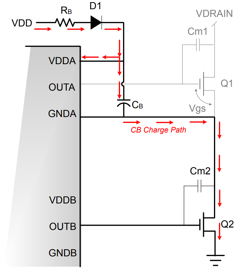
In the first stage (lower switch drive phase, with \(Q_1\) off and \(Q_2\) on), the bootstrap capacitor \(C_B\) is being charged. During this period, the charging current from the source \(V_{DD}\) flows into the driver chip's \(VDDA\) pin. Through the charging loop of the capacitor, it travels through the bootstrap resistor \(R_B\), diode \(D_1\), capacitor \(C_B\), and \(Q_2\) to the ground.
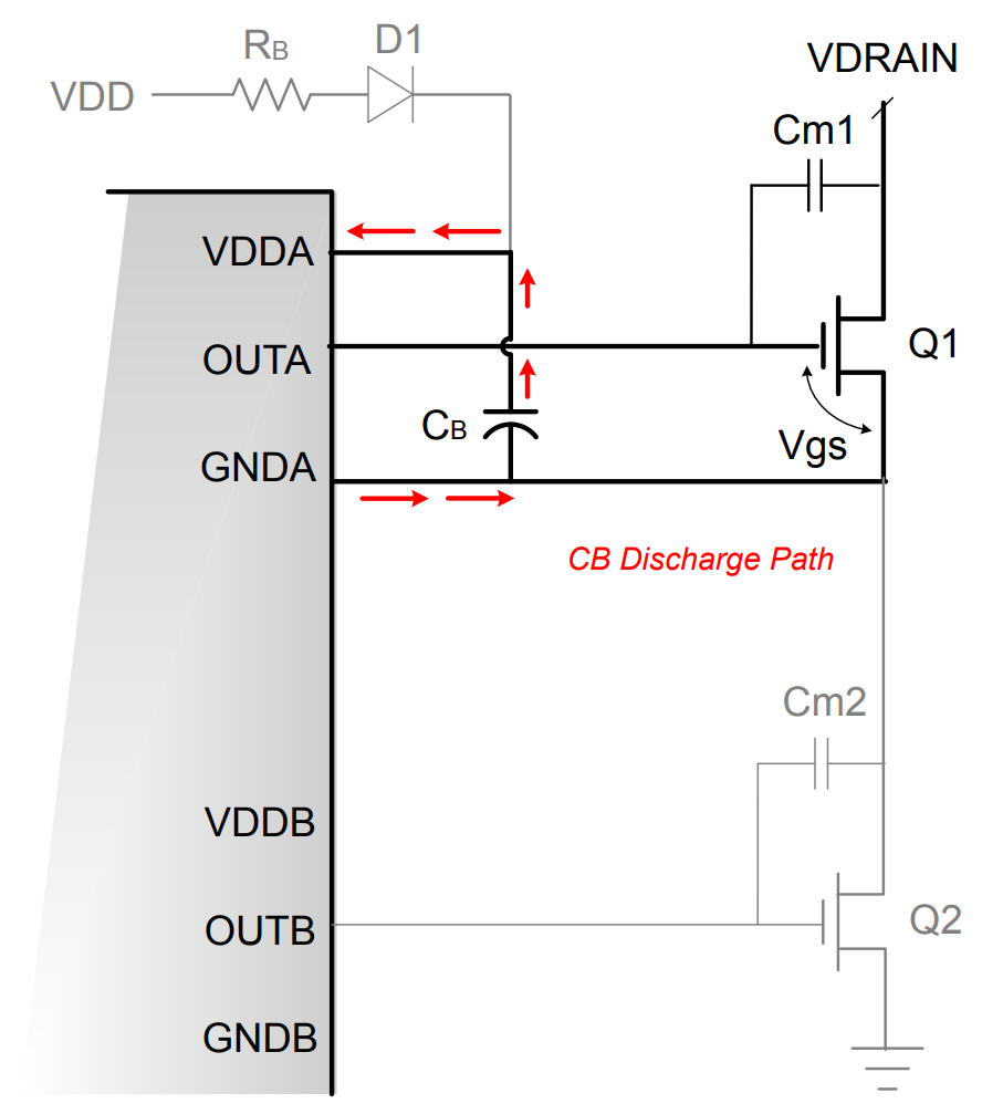
In the second stage (upper switch drive phase, with \(Q_2\) off and \(Q_1\) on), the voltage at the source terminal of \(Q_1\) (connected to GNDA pin) rapidly rises to the drain voltage VDRAIN. Because the voltage across the capacitor cannot change instantaneously, the voltage at VDDA is equal to the source voltage of \(Q_1 plus the voltage across \(C_B\) (\)C_B$ has been charged to approximately VDD–0.7V). As the source voltage of \(Q_1\) (and GNDA) rises, diode \(D_1\) becomes reverse-biased, disconnecting the connection between the VDD supply and \(C_B\). At this point, \(C_B\) supplies all the current required for the upper switch drive phase.
Bootstrap Circuit Design 🚧
🚧
References and Acknowledgments
- Understanding Bootstrap Circuit Principles in One Article
- AN486: High-Side Bootstrap Design Using ISODrivers in Power Delivery Systems
Original: https://wiki-power.com/ This post is protected by CC BY-NC-SA 4.0 agreement, should be reproduced with attribution.
This post is translated using ChatGPT, please feedback if any omissions.