Power Supply Design - Ripple Noise and Measurement Methods
Ripple and Noise in Power Supplies
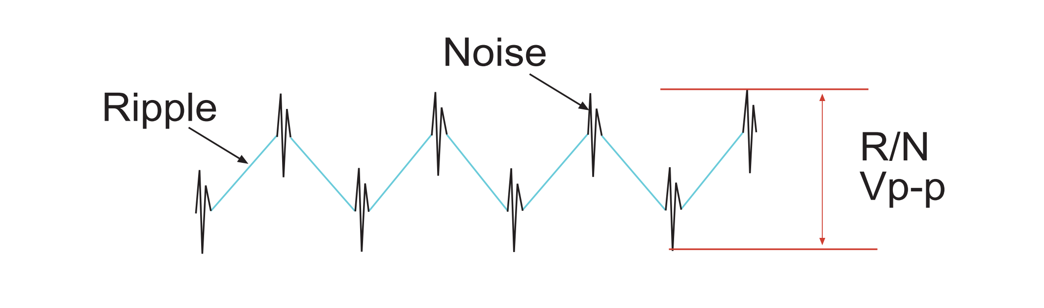
Ripple is generated by the charging and discharging of the output filtering capacitor and typically has a frequency corresponding to the power supply's operating frequency or twice that frequency, depending on the topology. Noise, on the other hand, is usually superimposed at the inflection points of the ripple and is produced by parasitic effects every time the switching state changes. Ripple and noise are commonly measured together and are expressed in units of mVpp.
For applications requiring a power supply with very low ripple and noise, it is often necessary to add a high-speed LDO (Low Drop-Out) regulator after the output voltage, which demands a high PSRR (Power Supply Rejection Ratio) value of over 70dB. For an introduction to PSRR and its measurement, you can refer to the article on Power Supply Design - LDO Power Supply Rejection Ratio (PSRR) and Measurement Methods.
Testing Methods
Considerations when using an oscilloscope to measure ripple and noise:
- Probes:
- If possible, it is recommended to use active probes. Typically, 1x probes are used (with peak-to-peak values in the mV range) to avoid introducing measurement errors due to probe attenuation.
- Keep the ground lead as short as possible and connect it in parallel with the output capacitor for measurement.
- Coupling Mode: AC coupling
- Bandwidth: 20MHz
- Digital Filters: Enable 1MHz capture and triggering
References and Acknowledgments
Original: https://wiki-power.com/
This post is protected by CC BY-NC-SA 4.0 agreement, should be reproduced with attribution.This post is translated using ChatGPT, please feedback if any omissions.