Power Supply Topology - Switching Voltage Regulator (Non-isolated)
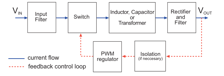
A switching power supply is a type of power supply that uses the time ratio of opening and closing of electronic switches to maintain a stable output voltage. Modern switching power supplies are generally composed of pulse width modulation (PWM) control ICs and MOSFETs.
Basic Concepts of Switching Voltage Regulation
- Time for one complete cycle: \(T_{s}\)
- Time for electronic switch to be turned on: \(T_{on}\)
- Duty cycle \(\delta=\frac{T_{on}}{T_{s}}\)
Volt-second balance of inductance: For an inductance in a stable state, the product of the volt-seconds during the on time (rising current segment) of the switch must be equal to the product of the volt-seconds during the off time (falling current segment) of the switch.
Power equality principle: Without considering efficiency, the input power of a switching power supply is equal to the output power, which is equivalent to the product of input voltage and current, or the product of output voltage and current. Intuitively, a buck converter can provide a larger current than the input, while a boost converter has an output current smaller than the input.
Main Components and Characteristics of Switching Voltage Regulation
The main components used in switching voltage regulation are electronic switches, inductors, and capacitors.
Electronic Switches
The requirement for electronic switches is to achieve fast switching on and off, the faster the better. Commonly used devices include transistors, power MOSFETs, or IGBTs.
Inductors
Inductors, as energy storage components, are used in DC-DC converters to smooth the current (also known as choke coils). The current flowing through the inductor has the characteristic of magnetic flux continuity (which can be understood as inertia). In most cases, the inductor operates in its linear region, where the inductance value remains constant and does not change with terminal voltage and current. Inductors have the following characteristics:
- When there is a current \(I\) flowing through an inductor \(L\), it stores energy of \(\frac{1}{2}LI^2\).
- When the voltage \(V\) across the inductor \(L\) is constant, because \(V=L\frac{di}{dt}\), neglecting internal resistance, the rate of change of inductor current is \(\frac{di}{dt}=\frac{V}{L}\), which means the inductor current increases linearly.
- For an inductor that is storing energy, if the original circuit is suddenly disconnected, the inductor will maintain the magnetic field, which means the current cannot change instantaneously, or in other words, the volt-second value remains constant.
The power stored in an inductor can be expressed as:
It can be seen that the power stored in an inductor is directly proportional to the switching frequency. If the switching frequency doubles, the size of the inductor can be halved.
Capacitors
Capacitors in DC-DC converters are also used for energy storage and transfer, but unlike inductors, they have the opposite frequency characteristics. They are mainly used to absorb ripple and smooth the voltage waveform, making the output voltage stable. They are also referred to as output capacitors.
The power stored in a capacitor can be expressed as:
Similar to inductors, capacitors can be made smaller by increasing the switching frequency. However, it should be noted that higher switching frequencies generally generate higher noise, so a balance needs to be struck between size and frequency.
Diodes
In non-synchronous DC-DC converters, diodes are used to provide a current path for the inductor when the switch is turned off, so they are also called freewheeling diodes. In synchronous DC-DC converters, electronic switches are used instead of freewheeling diodes.
Non-isolated DC-DC Topology
In non-isolated DC-DC topology, the input source and output load share the same current path.
By using electronic switches, inductors, capacitors, and diodes, the simplest PWM-type DC-DC converters can be constructed. They are mainly divided into three types: buck converters, boost converters, and buck-boost converters. The following will provide detailed explanations. There are also dual-phase inverting buck-boost converters (Cuk), and dual-phase forward buck-boost converters (SEPIC), but they are less commonly used and will not be described in detail.
Buck Converter
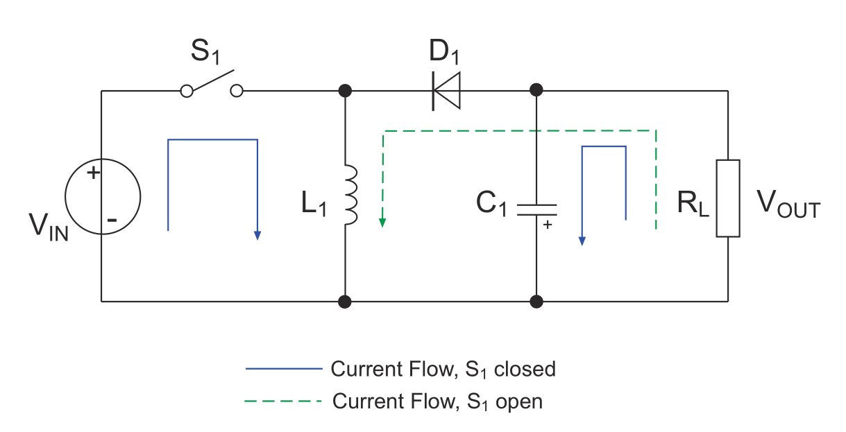
A buck converter converts a higher voltage into a stable lower voltage. The topology is as follows:
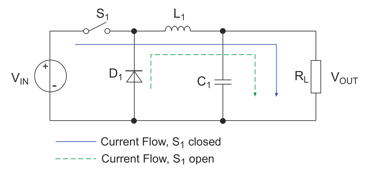
Note: The switch \(S_1\) in the diagram is actually an electronic switch (such as a power MOSFET), but for ease of understanding, it is simplified as a regular switch.
Basic principle:
Translate into English:
- Close switch \(S_1\) (solid blue line)
- At this time, diode \(D_1\) is cut off, and the current passes through inductor \(L_1\) to supply power to the load \(R_L\), while storing energy in inductor \(L_1\) and capacitor \(C_1\). Before the inductor coil saturates, the current increases linearly (the current inside the inductor cannot change abruptly), and the output voltage cannot immediately reach the input voltage value.
- The forward volt-second of the inductor at this time is: \((V_{in}-V_{out})* T_{on}\)
- Open switch \(S_1\) (dashed green line)
- Due to the self-inductive effect of inductor \(L\), the direction and magnitude of the current cannot change abruptly. At this time, the current will flow through the circuit provided by the freewheeling diode \(D_1\) to continue to supply power to the output load. At the same time, capacitor \(C_1\) also participates in discharging.
- The reverse volt-second of the inductor at this time is: \(V_{out} * T_{off}\)
According to the volt-second balance of the inductor (i.e., energy conservation), \((V_{in}-V_{out})* T_{on}=V_{out} * T_{off}\), we can obtain:
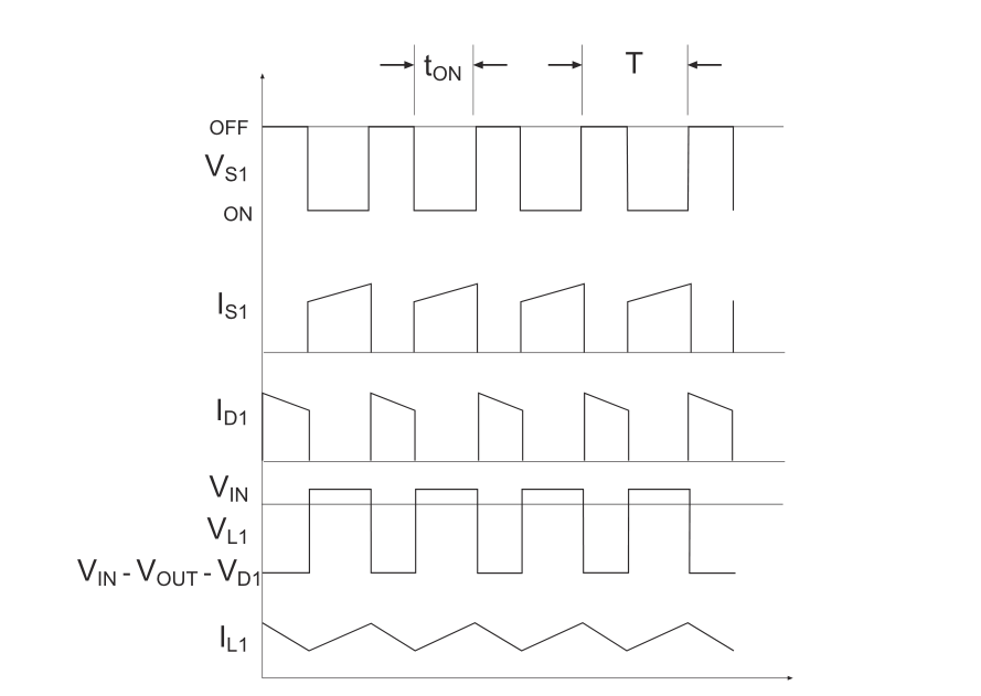
Waveform curves of each node:
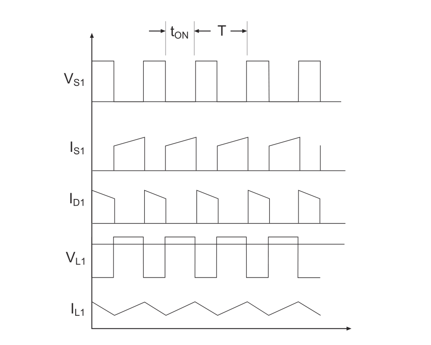
By controlling the duty cycle of PWM, the electronic switch \(S_1\) is continuously closed and opened, and the input current is pulsating. However, through the combined action of inductors, capacitors, and diodes, the output current is relatively continuous and stable.
Boost Converter
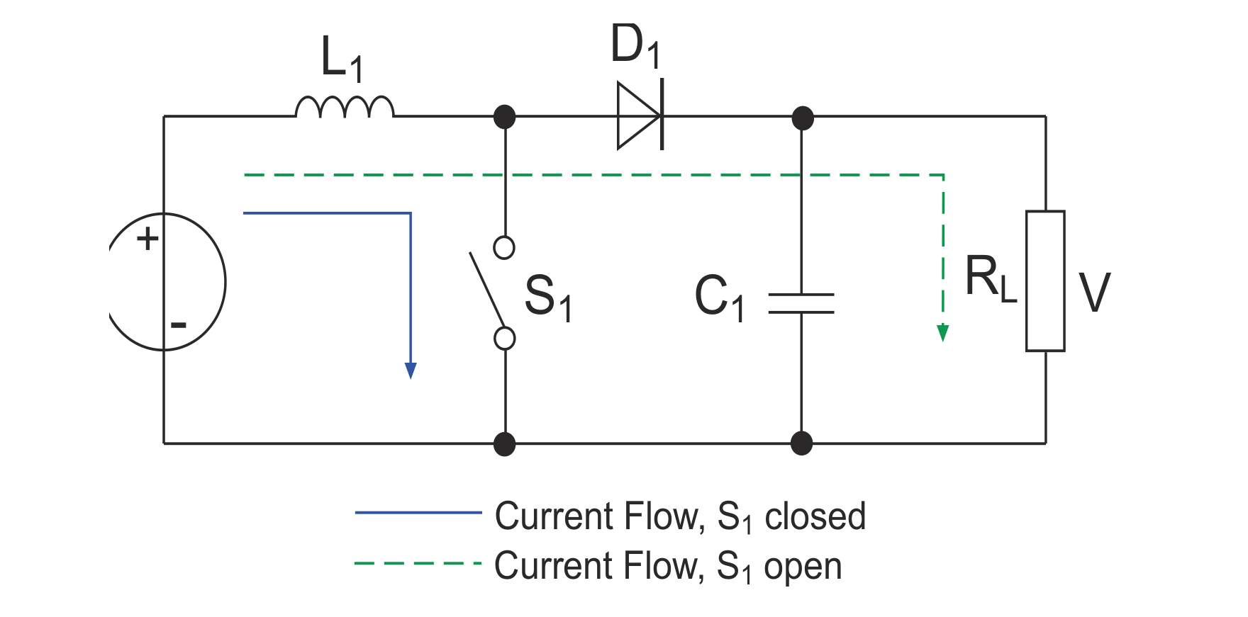
The boost converter can convert a lower voltage into a stable higher voltage. Its topology is as follows:
Basic principle:
- Close switch \(S_1\) (solid blue line)
- The current flows through inductor \(L_1\). Before the inductor saturates, the current increases linearly at a rate of \(\frac{V_{in}}{L_1}\), and the energy is stored in the inductor in the form of magnetic energy. At this time, capacitor \(C_1\) supplies power to the load \(R_L\), assuming that the voltage across the load is \(V_0\). Because switch \(S_1\) is closed, the anode of diode \(D_1\) is grounded, and the discharged charge from the capacitor cannot pass through the diode.
- The forward volt-second of the inductor at this time is: \(V_{in}* T_{on}\)
- Open switch \(S_1\) (dashed green line)
- Since the current on inductor \(L_1\) cannot change abruptly, the magnetic energy on the inductor is converted into voltage output current, which decreases linearly at a rate of \(\frac{V_{out}-V_{in}}{L_1}\) and is connected in series with the power supply \(V_{in}\) to supply power to capacitor \(C_1\) and load \(R_L\). When the series voltage is higher than \(V_0\), capacitor \(C_1\) is in the charging state; when the series voltage is equal to \(V_0\), the charging current is zero; when \(V_0\) is decreasing, the capacitor discharges to maintain \(V_0\) constant.
- The reverse volt-second of the inductor at this time is: \((V_{out}-V_{in})* T_{off}\)
According to the volt-second balance of the inductor \(V_{in}* T_{on}=(V_{out}-V_{in})* T_{off}\), we can obtain:
(This equation holds only when \(V_{in}<V_{out}\))
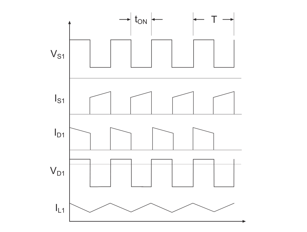
Waveform curves of each node:
Because the voltage \(V_0\) across the load in series is higher than the original \(V_{in}\), it can achieve boost.
Buck-Boost Converter
The buck-boost converter can convert an input voltage into a stable output voltage with the opposite phase, which can be higher or lower than the input voltage. Its topology is as follows:
Basic principle:
Translate into English:
- Close switch \(S_1\) (solid blue line)
- The current flows through inductor \(L_1\), and before the inductor saturates, the current increases linearly at a rate of \(\frac{V_{in}}{L_1}\); diode \(D_1\) is reverse biased, blocking the current from the power supply to the load. The energy stored in capacitor \(C_1\) powers the load during this time.
- The forward volt-second of the inductor at this time is: \(V_{in}* T_{on}\)
- Open switch \(S_1\) (dashed green line)
- Since the current in inductor \(L_1\) cannot change abruptly, it decreases linearly at a rate of \(\frac{V_{out}}{L_1}\), so the current flows through the green dashed loop, powering the load and charging capacitor \(C_1\), while diode \(D_1\) is forward biased. The current flowing through the inductor decreases linearly. Due to the direction of the current, the output voltage is negative with respect to ground, so the output of this topology is inverted.
- The reverse volt-second of the inductor at this time is: \(-V_{out}* T_{off}\)
Based on the inductor volt-second balance \(V_{in}* T_{on}=-V_{out}* T_{off}\), we can obtain:
Waveforms of each node:
The advantage of a buck-boost converter is that the input voltage can be lower or higher than the regulated output voltage. It can be used in battery-powered circuits, for example, when a system requires a 12V power supply and the battery voltage is fully charged at 13V or discharged to 11V.
Continuous and Discontinuous Modes of Buck and Boost Converters
Continuous conduction mode (CCM) and discontinuous conduction mode (DCM) refer to whether the current in the inductor will decrease to 0. If the load is large, the current in the inductor will not decrease to 0, and it is called continuous mode. Conversely, if the load is small and the converter has enough time to fully charge the output capacitor, then the current in the inductor will decrease to 0. When a new cycle starts, the current in the inductor will linearly increase from 0, and this is called discontinuous mode.
The critical state between continuous and discontinuous modes is \(\frac{1}{2}\Delta i_L=I_{out}\). When \(\frac{1}{2}\Delta i_L<I_out\), it is in continuous mode; otherwise, it is in discontinuous mode.
In the case of low load, the transition from continuous mode to discontinuous mode will cause a change in the relationship between input and output voltages:
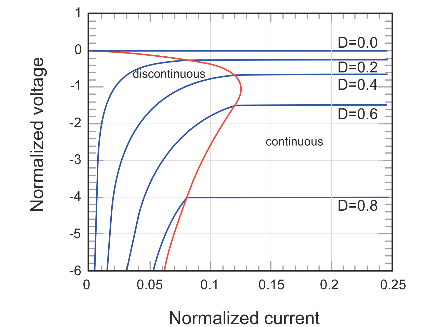
Therefore, to operate in continuous mode, many buck-boost controllers increase their operating frequency under low load conditions.
Synchronous and Asynchronous Conversion
The difference between synchronous and asynchronous conversion refers to whether a diode or a MOSFET is used as the reverse current protection rectifier. In the figure below, the left side is asynchronous, and the right side is synchronous:
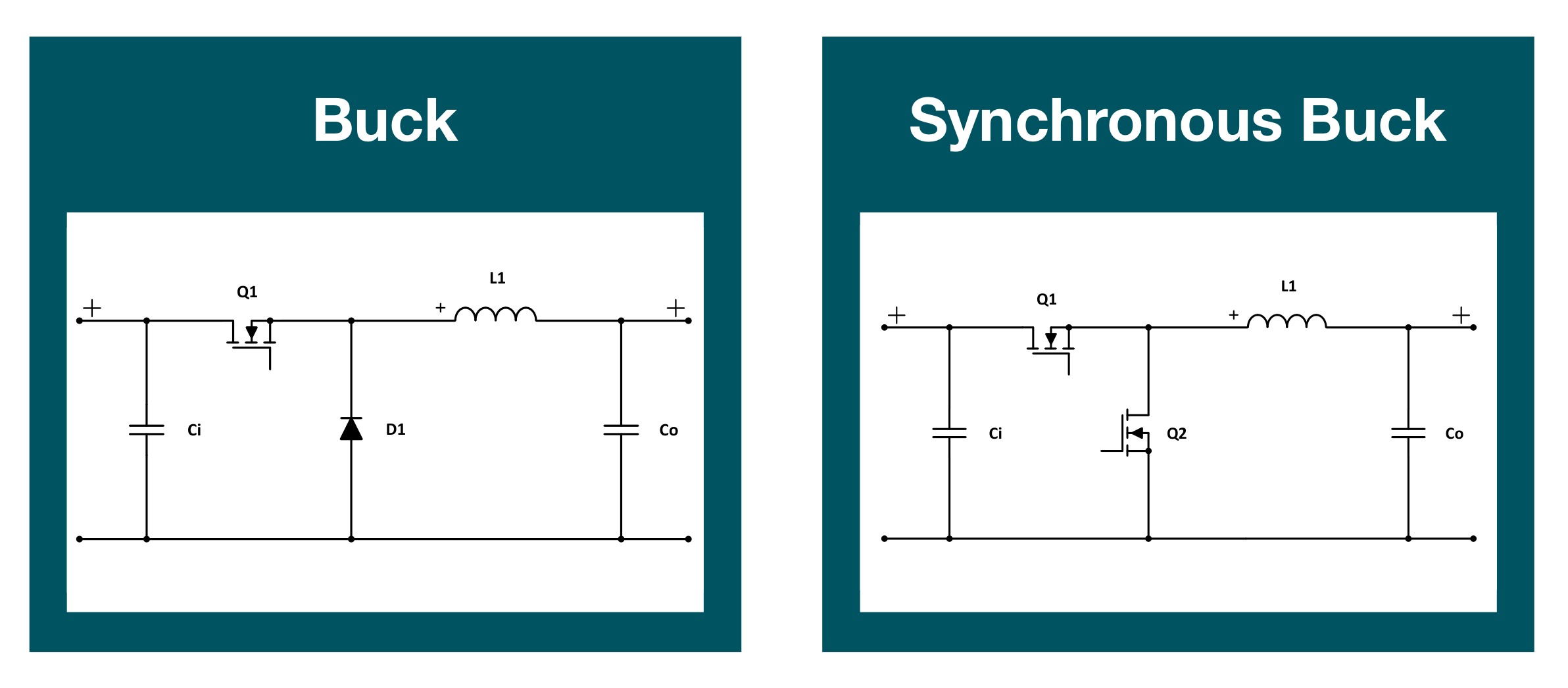
In synchronous mode, the startup signal of the MOSFET must be out of phase with the PWM signal.
The advantage of synchronous mode compared to asynchronous mode is that the MOSFET has a small \(R_{DS(on)}\) and a small forward voltage drop, resulting in higher efficiency under high current and input voltage conditions. Moreover, the package of high-power MOSFETs is generally smaller than that of power diodes, so it saves space.
The disadvantage of synchronous mode compared to asynchronous mode is that it brings additional drive circuits and timing circuits to prevent both MOSFETs from conducting at the same time, which increases the cost. In addition, in the case of low load, the charging and discharging of the MOSFET gate capacitance will generate additional power loss, so the efficiency is actually lower than that of asynchronous mode.
References and Acknowledgments
- Switching Power Supply Basics
- Introduction to Buck, Boost, and Buck-Boost Converters
- "Switching Power Supply Principles and Design"
- "DC-DC Converter Handbook and User Practical Tips"
- "Power-Topologies-Quick-Reference-Guide_TI"
Original: https://wiki-power.com/
This post is protected by CC BY-NC-SA 4.0 agreement, should be reproduced with attribution.This post is translated using ChatGPT, please feedback if any omissions.