Radio Frequency - S-Parameters
Scattering parameters, often referred to as S-Parameters, are used to characterize the behavior of reflected and transmitted signals in the frequency domain, including both their amplitude and phase. S-Parameters are represented as a complex matrix. We can think of the internal workings of a circuit as a black box, disregarding the internal circuit elements, and use S-Parameters to measure its port characteristics.
Detailed Explanation of S-Parameters
The naming convention for S-Parameters involves the first number representing the measurement port, and the second number representing the reference port. For example, S21 represents the signal at port 2 when excited relative to port 1. The form of the S-Parameter wave can be power, voltage, or current.
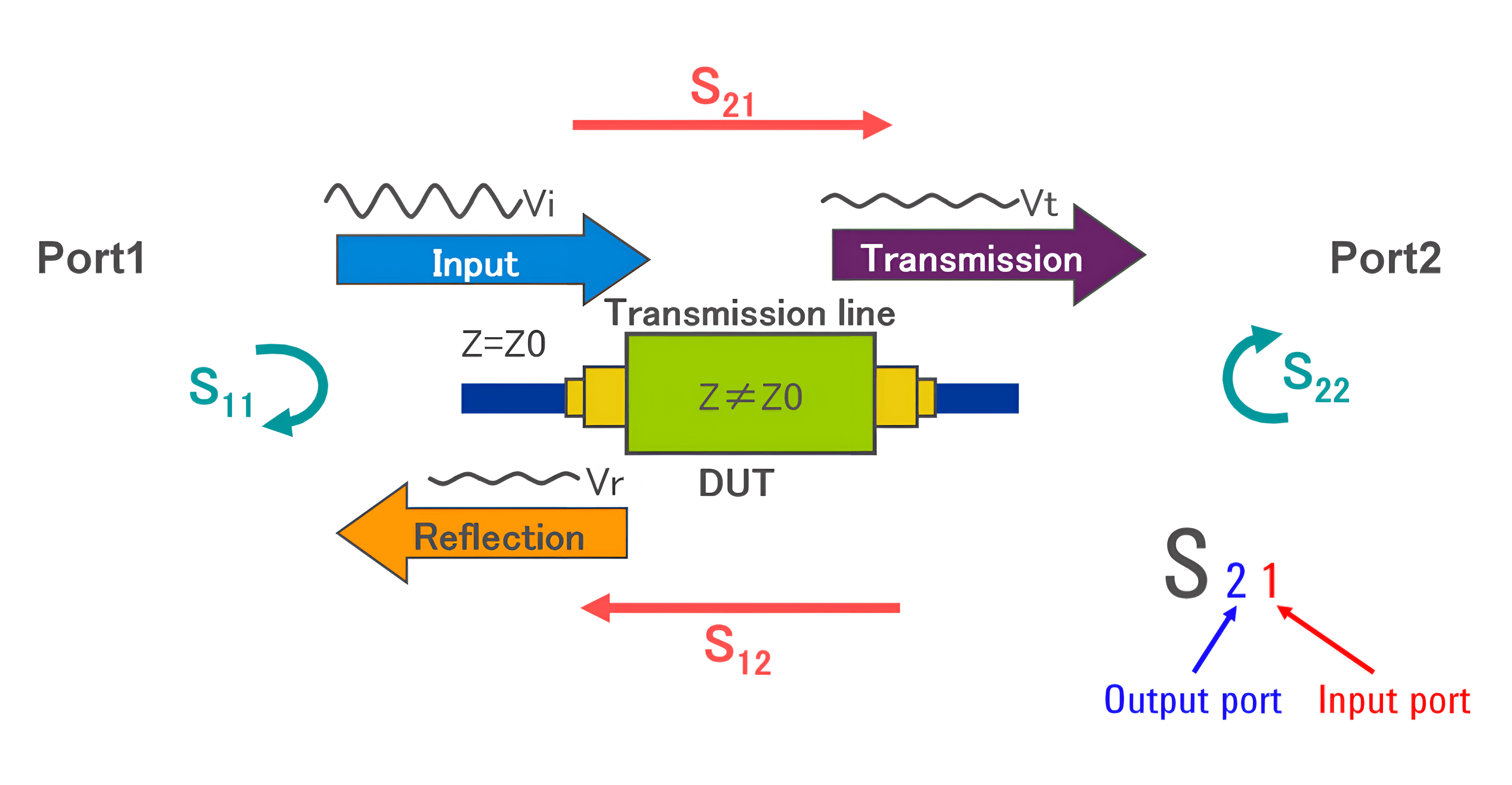
As shown in the image above, S11 and S22 represent the reflection coefficients (reflection/input), while S21 and S12 represent the transmission coefficients (transmission/input).
S11
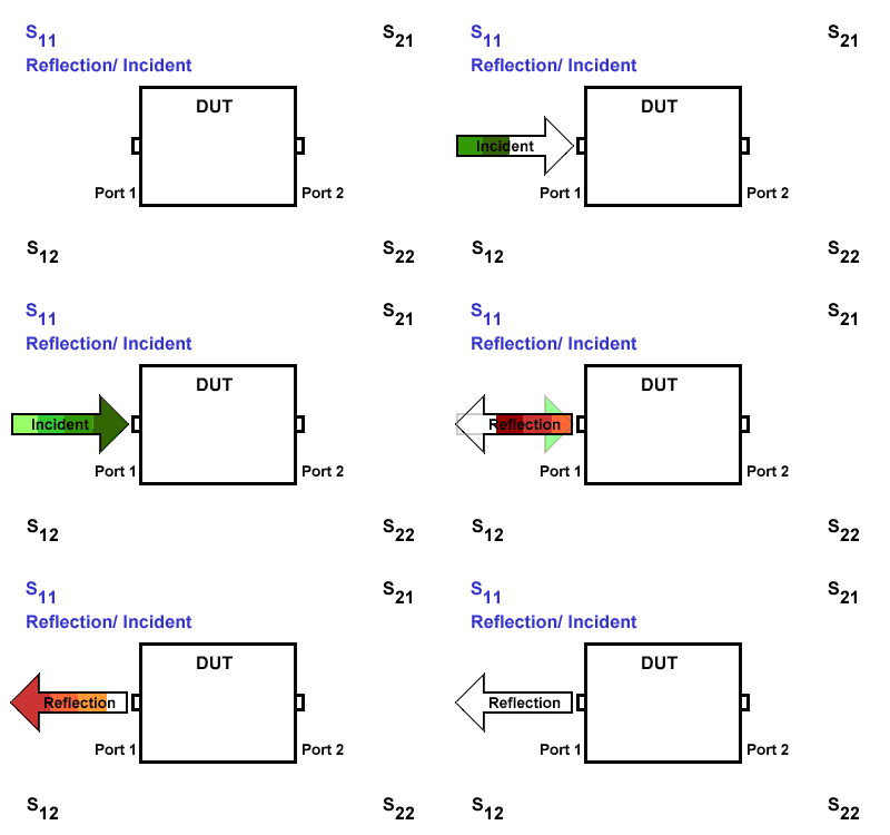
S11 refers to the reflection signal at port 1 concerning the incident signal at port 1. It is defined as \(S11=\frac{S_{Reflection}}{S_{Incident}}\).
S21
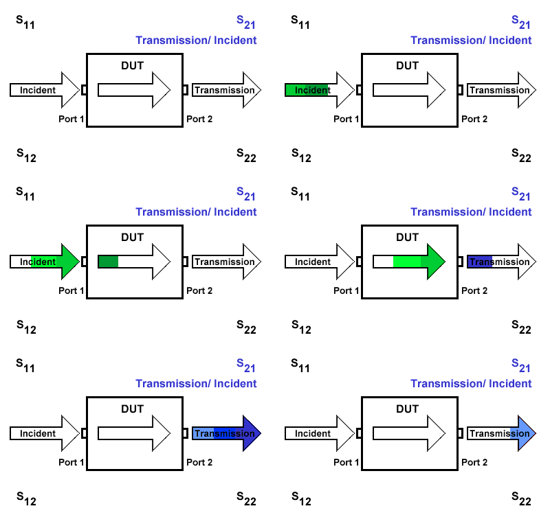
S21 represents the transmission signal at port 2 concerning the incident signal at port 1. It is defined as \(S21=\frac{S_{Transmission}}{S_{Incident}}\).
S12
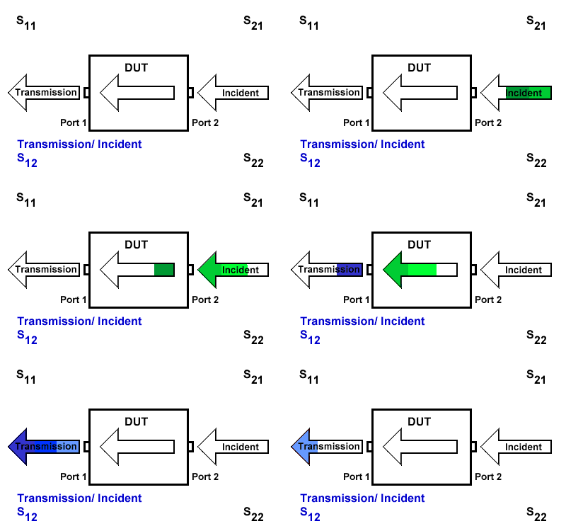
S12 indicates the transmission signal at port 1 concerning the incident signal at port 2. It is defined as \(S12=\frac{S_{Transmission}}{S_{Incident}}\).
S22
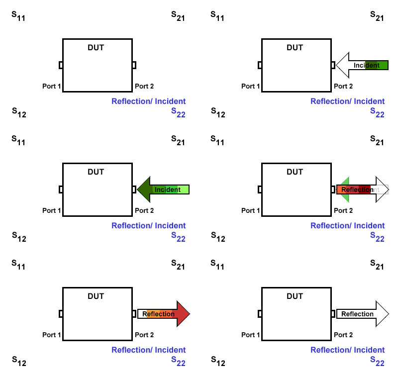
S22 refers to the reflection signal at port 2 concerning the incident signal at port 2. It is defined as \(S22=\frac{S_{Reflection}}{S_{Incident}}\).
References and Acknowledgments
- Meaning and Practical Measurement of S-Parameters
- "S-Parameter Measurements Basics for High-Speed Digital"
Original: https://wiki-power.com/ This post is protected by CC BY-NC-SA 4.0 agreement, should be reproduced with attribution.
This post is translated using ChatGPT, please feedback if any omissions.