RF - Resonant Circuit - Basic Definition
In this major section, we will study parallel resonant circuits and their characteristics in RF, the concept of quality factor (Q), and its relationship with source impedance and load impedance. We will also study the losses of components and how they affect the circuit, and finally, we will demonstrate some coupled resonant circuits.
Resonant circuits are used in RF circuits in every transmitter, receiver, and test equipment to selectively pass a certain frequency or group of frequencies from the source to the load while attenuating all other frequencies outside the passband. An ideal resonant circuit looks like this:
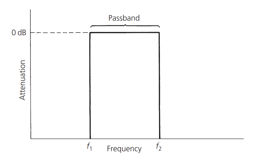
It is a perfect rectangular passband with wireless attenuation when the frequency is lower or higher than the target bandwidth, while allowing the signals within the target passband to pass without interference. However, due to the physical properties of the components that make up the filter, a perfect filter is not possible, but we can design non-ideal filters that meet the requirements.
Bandwidth
Bandwidth generally refers to the half-power bandwidth, which is the difference between the upper and lower frequencies at which the amplitude response is 3dB lower than the passband response, as shown in the figure:
Meaning and Calculation of dB
dB is a relative value that can represent large or small numbers concisely. For example, if we want to represent a power change that increases by 100,000,000 times, we only need to write +80dB.
Where \(P_1\) represents the current power and \(P_0\) represents the reference power. If \(P_1\) is twice \(P_0\), then:
If \(P_1\) is half of \(P_0\), then:
Similarly, +10dB represents a 10 times increase in power, and -10dB represents a decrease in power to 1/10.
3dB often appears in power graphs or error rate graphs, where +3dB means doubling and -3dB means halving.
dBm and dBw
dBm and dBw are obtained by replacing the reference power \(P_0\) in the dB formula with 1 mW and 1 W, respectively:
Since 1 mW and 1 W are both fixed values, dBm and dBw can represent the absolute value of power.
There is a conversion table between current power and dBm, dBw:
| watt | dBm | dBw |
|---|---|---|
| 0.1 pW | -100 dBm | -130 dBW |
| 1 pW | -90 dBm | -120 dBW |
| 10 pW | -80 dBm | -110 dBW |
| 100 pW | -70 dBm | -100 dBW |
| 1 nW | -60 dBm | -90 dBW |
| 10 nW | -50 dBm | -80 dBW |
| 100 nW | -40 dBm | -70 dBW |
| 1 μW | -30 dBm | -60 dBW |
| 10 μW | -20 dBm | -50 dBW |
| 100 μW | -10 dBm | -40 dBW |
| 794 μW | -1 dBm | -31 dBW |
| 1.000 mW | 0 dBm | -30 dBW |
| 1.259 mW | 1 dBm | -29 dBW |
| 10 mW | 10 dBm | -20 dBW |
| 100 mW | 20 dBm | -10 dBW |
| 1 W | 30 dBm | 0 dBW |
| 10 W | 40 dBm | 10 dBW |
| 100 W | 50 dBm | 20 dBW |
| 1 kW | 60 dBm | 30 dBW |
| 10 kW | 70 dBm | 40 dBW |
| 100 kW | 80 dBm | 50 dBW |
| 1 MW | 90 dBm | 60 dBW |
| 10 MW | 100 dBm | 70 dBW |
Among them, the most commonly used is 1 W = 30 dBm.
dBi, dBd, and dBc
The calculation methods of dBi, dBd, and dBc are similar to dB, indicating relative power values, but the meanings represented by the reference base \(P_0\) are different.
| dBx | Reference Base |
|---|---|
| dBi (Decibe-Isotropic) | Isotropic antenna |
| dBd (Decibe-Dipole) | Dipole antenna |
| dBc (Decibe-Carrier) | Carrier |
For the same gain, dBi is generally 2.15 larger than dBd, and this difference is due to the different directionalities of the two antennas.
Quality Factor (Q) of Resonant Circuit
This Q is different from the Q defined in the previous article. Q is a measure of the selectivity of a resonant circuit. The higher the Q value, the narrower the bandwidth, and the higher the selectivity of the resonant circuit. The formula for Q is defined as follows:
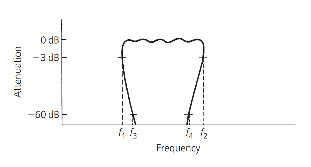
Shape Factor (SF)
The shape factor of a resonant circuit is usually defined as the ratio of the 60 dB bandwidth to the 3 dB bandwidth. For example, if the 60 dB bandwidth \(f_4 - f_3\) is 3 MHz and the 3 dB bandwidth \(f_2-f_1\) is 1.5 MHz, then the shape factor is:
The shape factor is a way to measure the steepness of the skirt edge. The smaller the number, the steeper the response of the skirt edge. The shape factor of a perfect filter is 1, which is the ultimate value. It is physically impossible to have a shape factor smaller than 1 in the passband, as shown in the following figure:
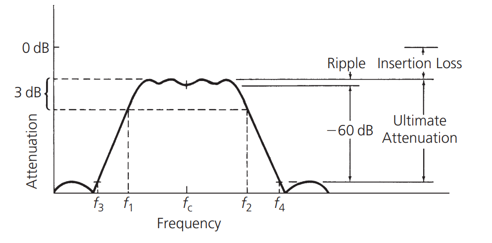
Ultimate Attenuation
Refers to the difference between the peak attenuation outside the passband and the passband. Due to the actual physical characteristics of the components, the ultimate attenuation cannot be infinite.
Insertion Loss
Refers to the attenuation loss caused by the components between the signal source and the end. In the case of impedance mismatch, some of the signals at the source end will be absorbed by these components, resulting in attenuation, which is expressed in dB.
Ripple
Ripple represents the flatness of the passband of a resonant circuit, expressed in dB. Its value is defined as the difference between the maximum attenuation and the minimum attenuation in the passband.
References and Acknowledgements
- "RF-Circuit-Design(second-edition)_Chris-Bowick"
- Understanding the Difference between dB, dBm, and dBw in 100 Minutes
Original: https://wiki-power.com/ This post is protected by CC BY-NC-SA 4.0 agreement, should be reproduced with attribution.
This post is translated using ChatGPT, please feedback if any omissions.