Radio Frequency - Components and Systems - Conductors
In radio frequency (RF) circuits, basic components like resistors, capacitors, and inductors exhibit more than just their individual resistive, capacitive, or inductive properties. We'll begin our analysis with the most fundamental component.
There are various forms of conductors in RF circuits, and the behavior of conductors in the RF spectrum largely depends on their diameter and length. In the AWG (American Wire Gauge) specification, each wire gauge is associated with a specific diameter (with a 6-unit difference in AWG value corresponding to a twofold difference in the English system diameter):
| AWG Value | Diameter (mil) |
|---|---|
| 50 | 1 |
| 44 | 2 |
| 38 | 4 |
| 32 | 8 |
| 36 | 16 |
| 20 | 32 |
| 14 | 64 |
Skin Effect
At low frequencies, the flow of electrons within a conductor covers the entire cross-section of the conductor. As the frequency increases, the strengthening of the magnetic field at the center of the cross-section introduces impedance to the electron flow, causing electrons to be pushed toward the edge. This results in a lower current density at the center compared to the edge, a phenomenon known as the skin effect. The skin effect is applicable to all conductors, including the pins of resistors, capacitors, and inductors.
The depth at which the current density in a conductor decreases to \(\frac{1}{e} (37\%)\) at the edge is referred to as the skin depth. This depth is a function of frequency, magnetic permeability of the conductor, and conductivity. Therefore, different conductors have different skin depths.
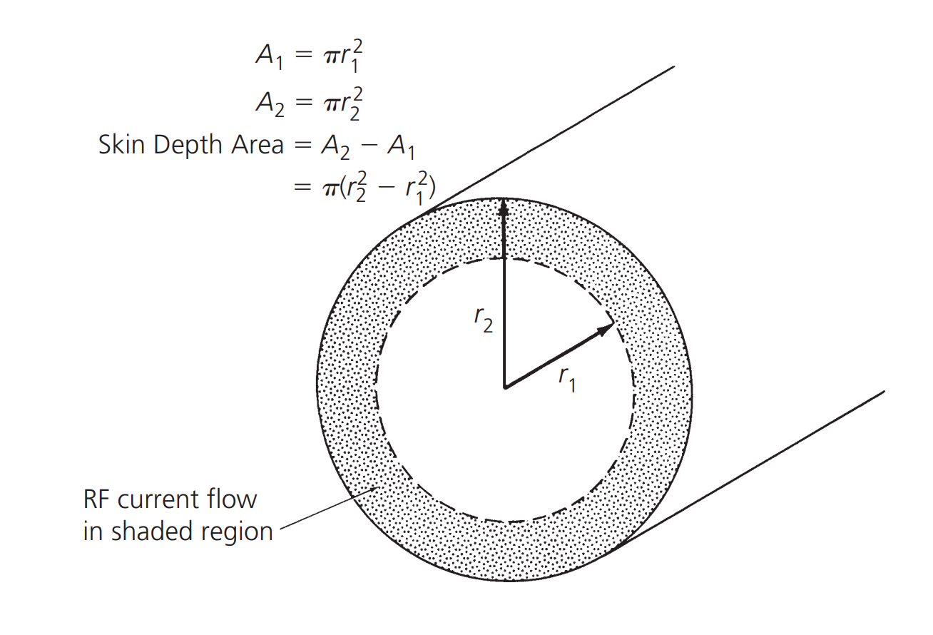
The impact of the skin effect is a reduction in the effective cross-sectional area of the conductor, resulting in increased AC impedance. For copper foil, the skin depth is approximately 0.85 cm at 60 Hz and about 0.007 cm at 1 MHz (meaning that 63% of the RF current flows within a width of 0.007 cm from the surface).
Straight-Line Inductance
Any current-carrying medium generates a magnetic field, and if it carries AC current, this magnetic field will alternate, inducing a voltage along the conductor that opposes changes in current. This phenomenon is known as self-inductance, and components exhibiting this property are referred to as inductors. While straight-line inductance may seem insignificant, it becomes significant at high frequencies.
The magnitude of straight-line inductance depends on length and diameter, and it is calculated using the following formula:
Where \(L\) is the inductance in microhenrys (\(\mu H\)), and the units for conductor length (\(l\)) and diameter (\(d\)) are centimeters (cm).
Inductance is a factor that cannot be overlooked in RF design. All inductors and RF circuits, including connecting wires and pins, exhibit inductance.
References and Acknowledgments
- "RF-Circuit-Design(second-edition)_Chris-Bowick"
Original: https://wiki-power.com/ This post is protected by CC BY-NC-SA 4.0 agreement, should be reproduced with attribution.
This post is translated using ChatGPT, please feedback if any omissions.