Semiconductor Test Basics - Functional Test
Functional Test is mainly used to verify the logical functions of a device. It is a type of test that uses test vectors and test commands. Compared to pure DC testing, the combination steps in functional testing are relatively complex and highly coupled.

During the functional test phase, the test system inputs test vectors to the Device Under Test (DUT) on a periodic basis. It compares the predicted results with the output data. If the actual results do not match the predicted values of the test vectors, the test is considered a failure.
Basic Concepts
Test Vectors
Test vectors, also known as test patterns, can be understood as the truth table of the logical functions designed for the device. Test vectors emphasize timing and are generally a series of input-output combinations. Inputs are typically represented by 0/1 for low/high levels, outputs are represented by L/H/Z for low/high/hi-Z states, and X represents no input or output.
Overall Functional Test
Functional Test Methods for Various Parameters
OS Test - Functional Test Method
Short circuit and open circuit are not considered as functions, but they can also be tested using functional test methods. The PMU and driver are turned off, and the test is performed using a current load and voltage receiver. The test schematic is as follows:
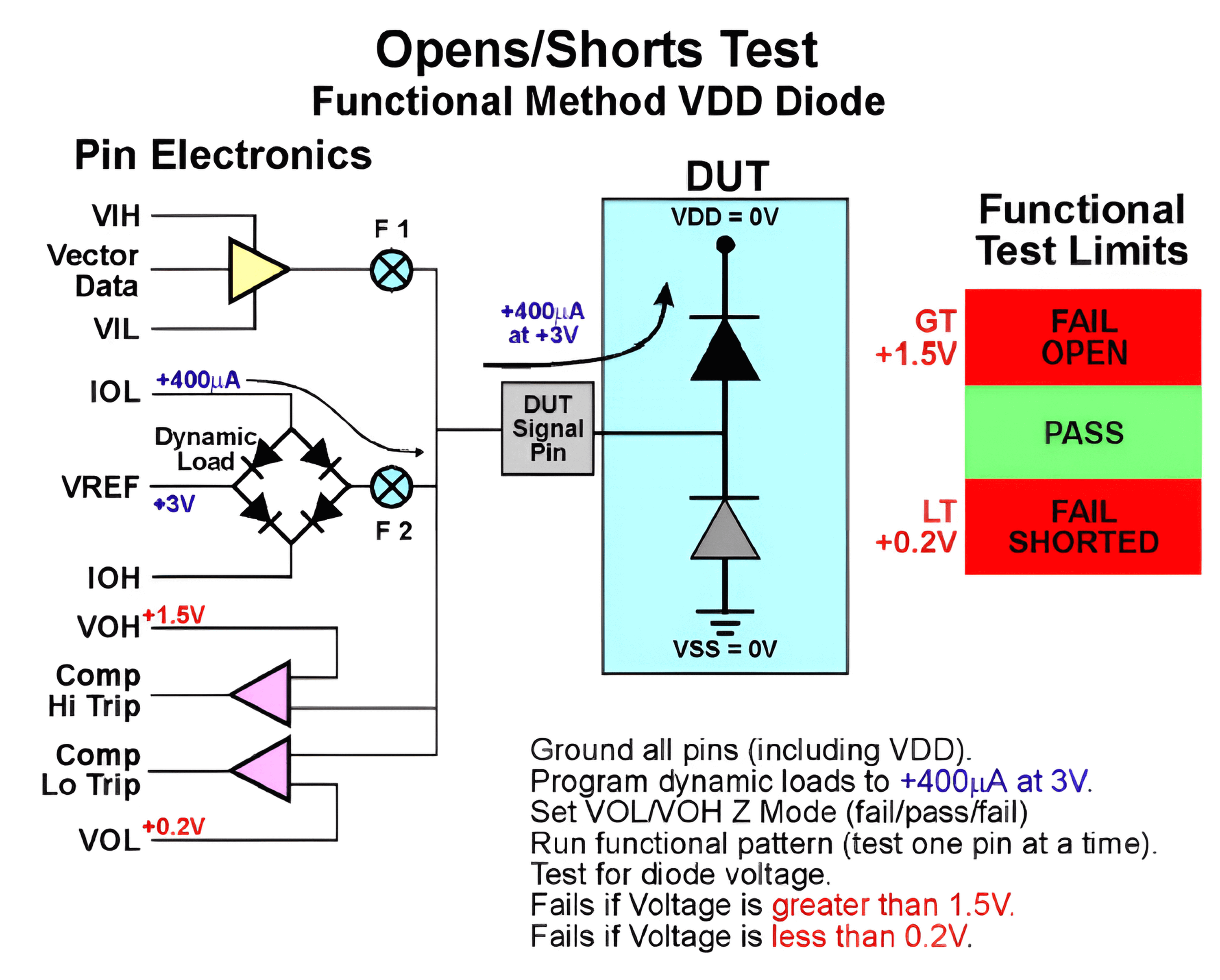
The test process is as follows:
- Ground all pins except the pin under test (power and signal pins).
- Define VOL/VOH (e.g., 0.2V/1.5V).
- Set the pin under test to output mode and disconnect it (hi-Z state).
- Provide VREF (3V) to generate dynamic load current (approximately 400µA) and measure the voltage on the pin under test.
- If the voltage is higher than VOH (+1.5V): Fail (Open)
- If the voltage is lower than VOL (+0.2V): Fail (Short)
- If the voltage is in the hi-Z state (voltage drop of approximately 0.65V after positive bias): Pass
- Reset the pin state and proceed to test the next pin.
The test vector pattern for this test is as follows:
00000   /* cycle 1 Ground all pins */
Z0000   /* cycle 2 Test the protection diode of the 1st pin */
0Z000   /* cycle 3 Test the protection diode of the 2nd pin */
00Z00   /* cycle 4 Test the protection diode of the 3rd pin */
000Z0   /* cycle 5 Test the protection diode of the 4th pin */
0000Z   /* cycle 6 Test the protection diode of the 5th pin */
/* The next cycle will be executed separately */
ZZZZZ   /* cycle 7 Disconnect all pins and test them */
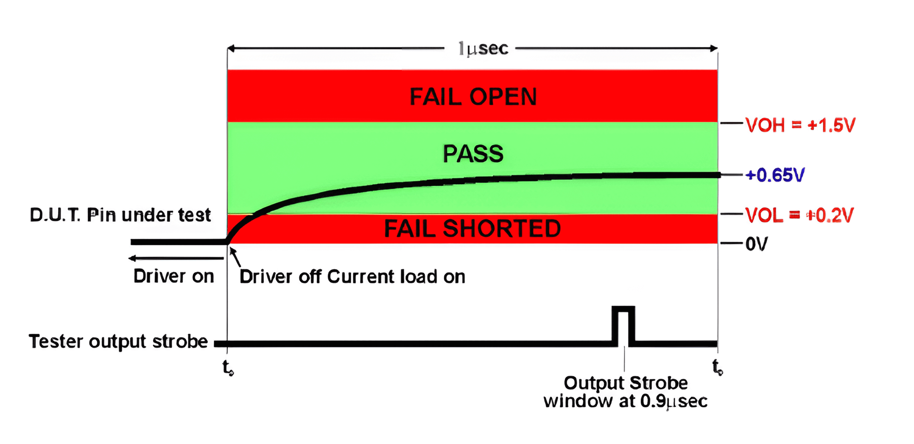
The schematic diagram below shows the normal voltage change and sampling. The sampling window is set to 0.9µs with a duration of 0.01µs to allow the voltage to stabilize before sampling:
Next, test the protection diodes to ground. It is only necessary to test for an open circuit (if there is a short circuit, it will definitely fail the previous test). The schematic diagram for testing the protection diodes to ground using the functional test method is as follows:
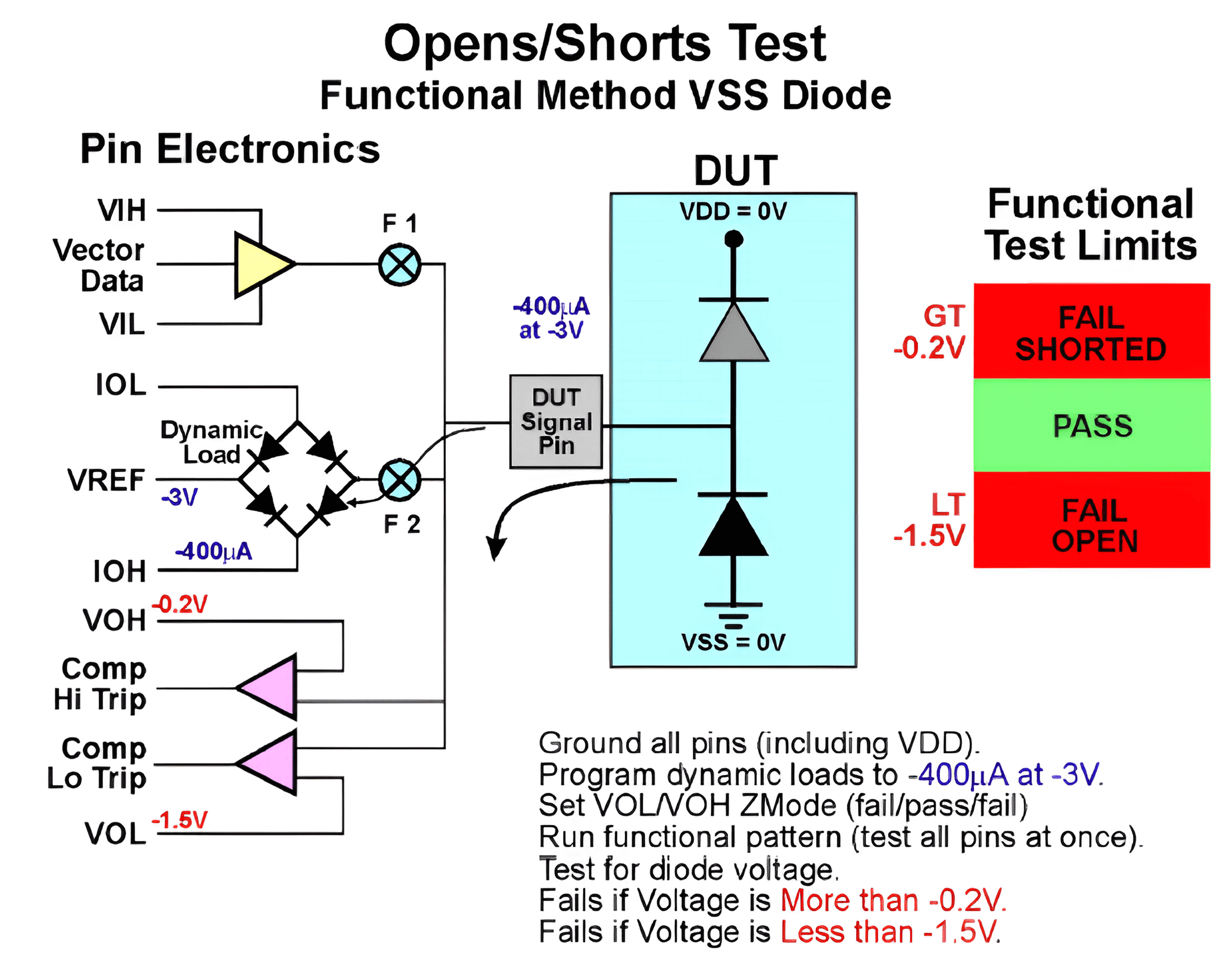
For this test, it is only necessary to run the 7th cycle (ZZZZZ) once to simultaneously test all the protection diodes to ground.
(DPS is used to pull down the pins to ground. If there is a fail-open condition, the measured voltage will be VREF instead of the clamped voltage. Do not confuse this with the DC method.)
VOL/IOL & VOL/IOH Test - Functional Test Method
The test schematic is as follows:
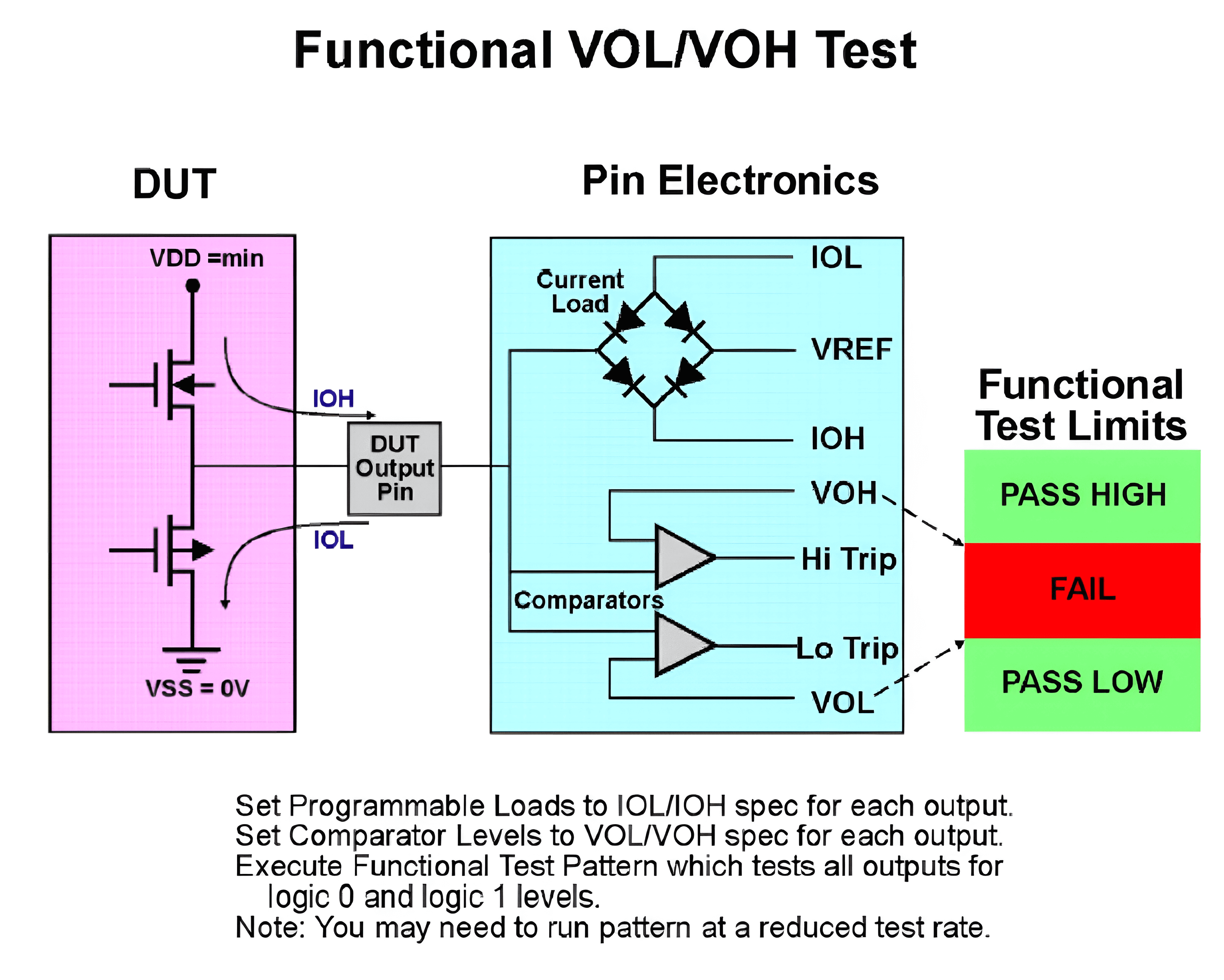
The test process is as follows:
Translate into English:
- Power supply VDDmin (??).
- Set VREF (mid-range value) to generate dynamic load current.
- Perform functional testing and monitor the voltage of the pins:
- Below VOH Spec or above VOL Spec: Fail
- Above VOL Spec: Fail
- Other range: Pass
VIL/VIH Testing - Functional Testing Method
VIL/VIH is to see if the DUT can correctly recognize the input logic. The schematic diagram for testing VIL/VIH using the functional testing method is as follows (assuming the left side of the chip is the input pin and the right side is the output, with input and output logic levels in phase):
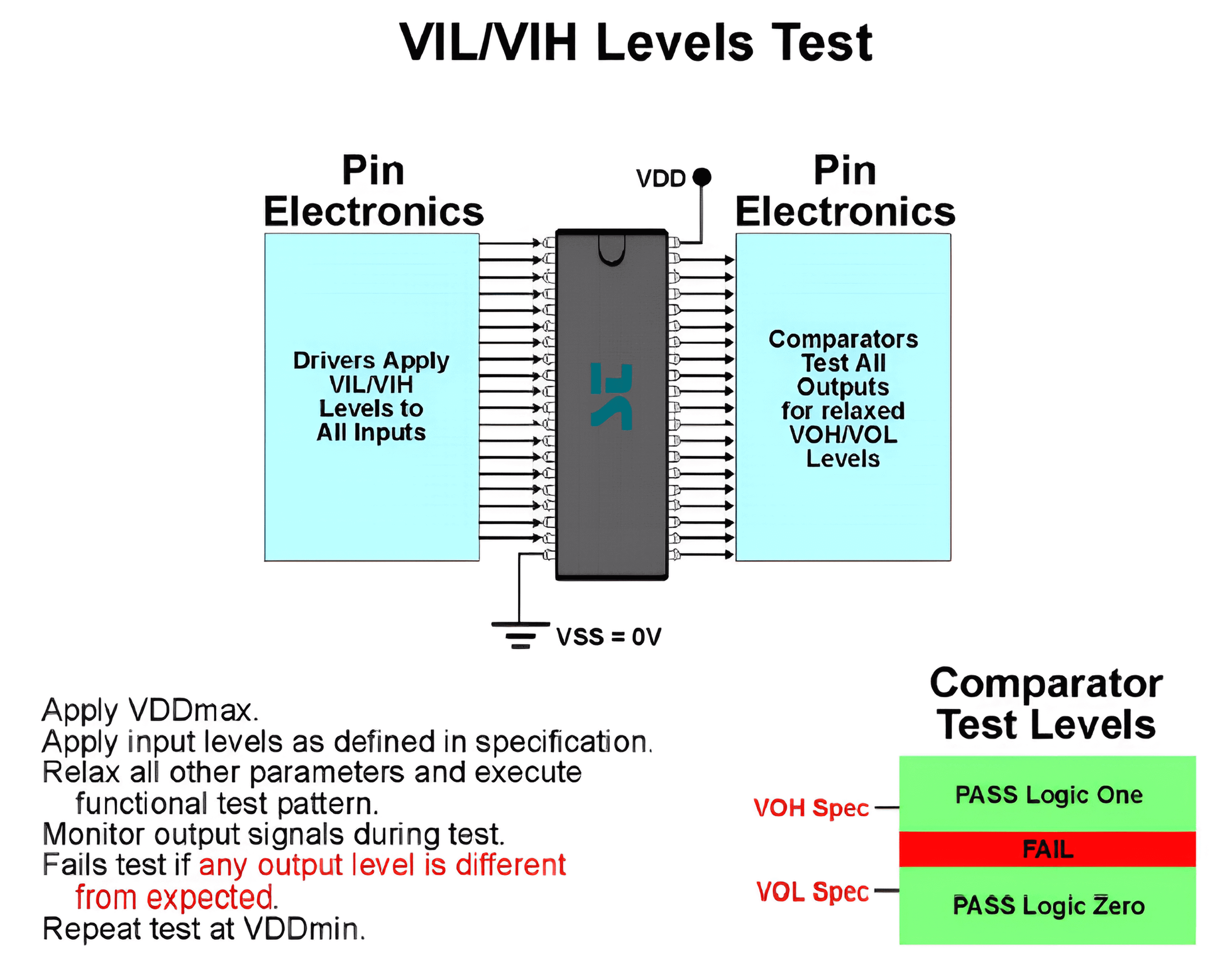
The process for testing VIL/VIH using the functional testing method is as follows:
- First, supply the DUT with VDDmax power.
- Apply the VIL/VIH nominal values to the pins, ensuring that other parameters have a certain margin.
- Perform functional testing and monitor the voltage of the output pins:
- Below VOH Spec: Fail
- Above VOL Spec: Fail
- Other range: Pass
- Supply the DUT with VDDmin power and repeat the above process.
If the test fails and the error cannot be identified, you can provide a larger margin to eliminate issues caused by other factors. For example, provide the optimal low level (0V) for VIL and the optimal high level (VDD) for VIH to see if the test can pass according to the process, and then gradually assign the original values of VIH/VIL to troubleshoot the problem.
IOZL/IOZH Testing - Functional Testing Method
The schematic diagram for testing IOZL/IOZH using the functional testing method is as follows:
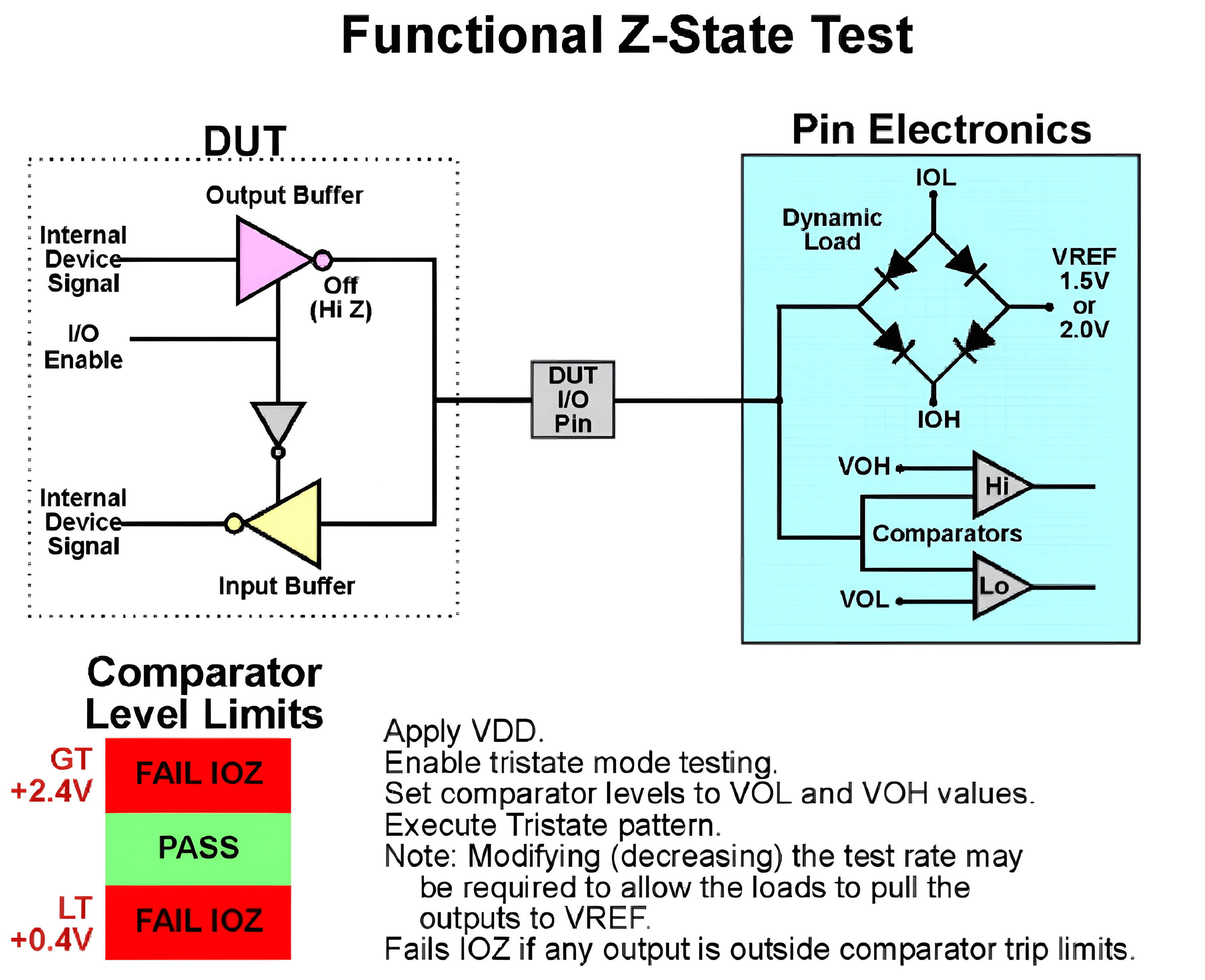
The testing process is as follows:
- Power the DUT with VDD and set the comparator values to VOL/VOH.
- Set VREF to generate dynamic load current and measure the pin voltage:
- Above VOH Spec: Fail
- Below VOL Spec: Fail
- Other range: Pass
References and Acknowledgements
- "The Fundamentals Of Digital Semiconductor Testing"
- "DC Test Theory"
Original: https://wiki-power.com/ This post is protected by CC BY-NC-SA 4.0 agreement, should be reproduced with attribution.
This post is translated using ChatGPT, please feedback if any omissions.