Signal Integrity - Impedance and Electrical Models
Impedance (Z) is the collective term for the hindrance offered by resistance, inductance, and capacitance in a circuit to alternating current. It is defined as the ratio of voltage to current (\(Z=V/I\)). Impedance is a complex quantity, with its real part called resistance and its imaginary part called reactance. In this context, the impedance resulting from capacitance in a circuit is known as capacitive reactance, while that resulting from inductance is called inductive reactance. The combination of capacitive and inductive reactance is referred to as impedance.
For a constant voltage, a higher impedance results in a smaller current, and vice versa. In extreme cases, an open circuit has an infinite impedance, while a short circuit has an impedance of zero. In interconnect lines, impedance is a critical factor affecting signal integrity. As a signal propagates, it responds continuously based on the instantaneous impedance.
Basic Electrical Models
When constructing basic electrical models, we consider the following ideal two-port components:
- Ideal resistor
- Ideal capacitor
- Ideal inductor
- Ideal transmission line
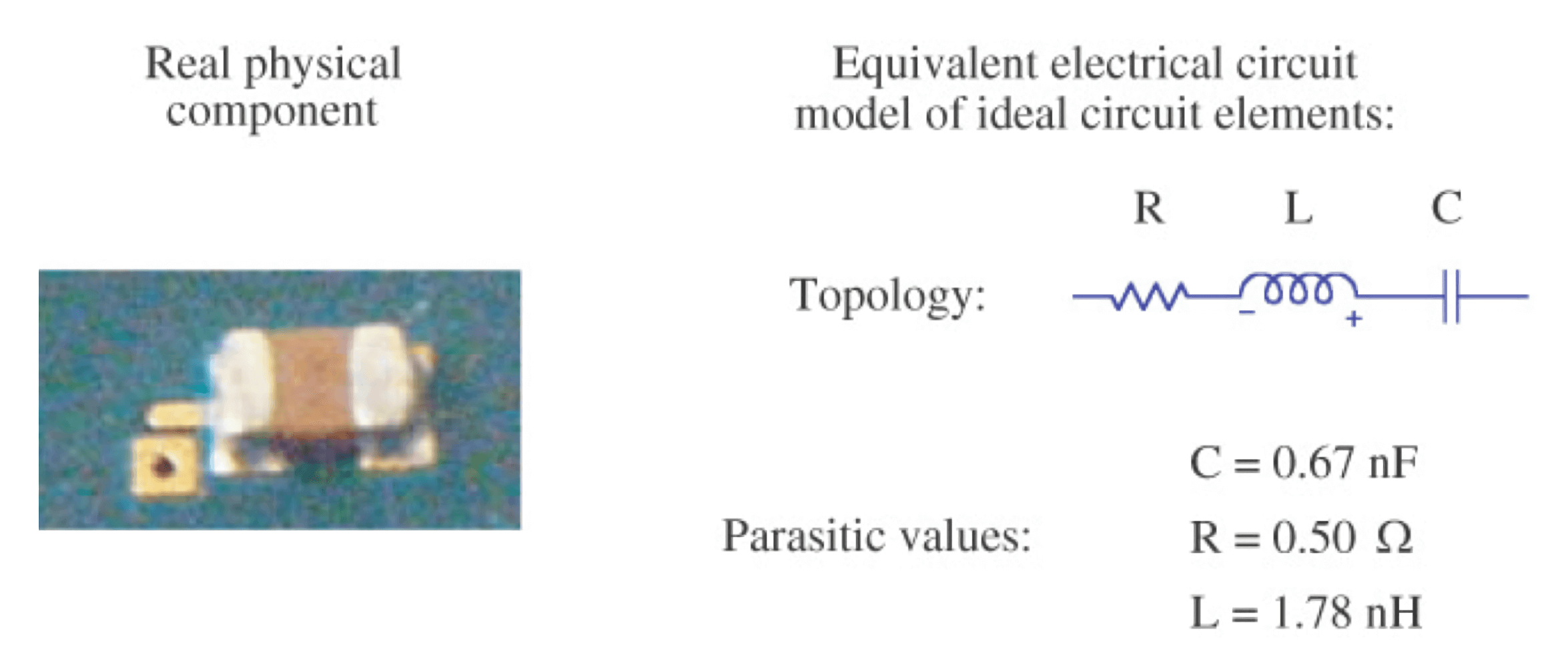
Among these, the characteristics of ideal resistors, capacitors, and inductors can be lumped together into one point, and they are termed lumped circuit elements. On the other hand, the characteristics of ideal transmission lines are distributed along the line. The goal is to create an equivalent circuit model that closely matches the measured impedance of actual components.
Time-Domain Impedance of an Ideal Resistor
The impedance of an ideal resistor is constant and its numerical value is equal to its resistance, independent of voltage and current.
Time-Domain Impedance of an Ideal Capacitor
For an ideal capacitor, there is a relationship between the charge stored between its plates and the voltage difference. The definition of capacitance is as follows:
Here, C represents capacitance (in Farads), Q represents the charge stored between the plates (in Coulombs), and V represents the voltage difference between the plates (in Volts).
The impedance of a capacitor is determined by the voltage across its terminals and the current flowing through it. In reality, there is no actual current flowing through the capacitor; it only appears as if there is current when the voltage across the capacitor's plates changes.
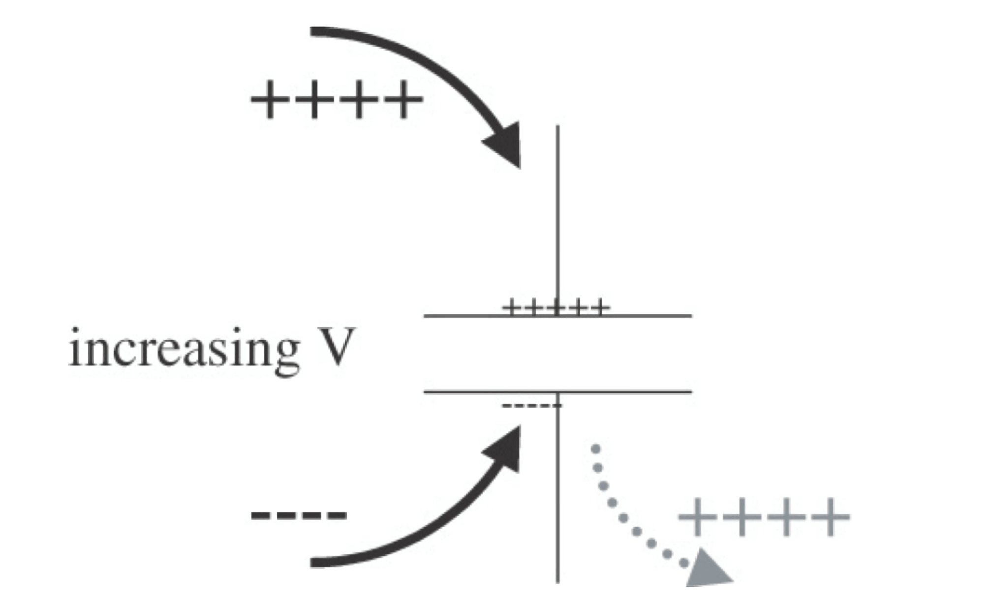
As shown in the above diagram, when positive charges accumulate on the top plate and negative charges accumulate on the bottom plate, the existing positive charges on the bottom plate are pushed out. This creates the appearance of current flowing through the capacitor. This current, which arises from the displacement of bound charges in a polarized dielectric, is called displacement current. It is not a real current but merely the movement of charges. Its definition is as follows:
From the above equation, it is clear that current only flows when the voltage across the capacitor's terminals changes. If the voltage remains constant, there will be no displacement current.
Therefore, the impedance of an ideal capacitor can be expressed as:
The impedance of a capacitor is influenced by the waveform of the voltage across its terminals. If the voltage changes rapidly (i.e., has a steep slope), the current through the capacitor is high, and the impedance is low. Conversely, when the voltage changes at a slower rate, with a higher capacitance value, the impedance is higher.
Time-Domain Impedance of an Ideal Inductor
For an ideal inductor, the voltage across its terminals is defined as:
Here, V represents the voltage across the inductor's terminals, L represents the inductance, and I represents the current flowing through the inductor. It is evident that the voltage across the inductor's terminals depends on the rate of change of the current, and the speed of the current change is determined by the voltage difference across the terminals. Whether the voltage difference across the terminals or the rate of change of current is the cause and effect depends on which is the driving source. The impedance of an inductor can be expressed as the ratio of the voltage across its terminals to the current flowing through it:
If the current through the inductor rapidly increases, the impedance becomes large, and vice versa. When the current is direct current (DC), the impedance approaches zero. Of course, the actual impedance of an inductor is closely related to the specific waveform of the current.
Impedance in the Frequency Domain
As seen earlier, the calculation formulas for impedance of inductors and capacitors in the time domain are relatively complex. However, when analyzed in the frequency domain, they become much simpler.
In frequency domain analysis, only sinusoidal waves exist, so we can analyze their interaction with ideal elements. Sinusoidal waves have three characteristics: frequency, amplitude, and phase. Typically, we use radians to describe these characteristics, and the relationship between angular frequency (\(\omega\)) and frequency (\(f\)) is:
We apply a sinusoidal voltage across the terminals of ideal components and observe the current flow. The impedance is still defined as the ratio of voltage to current, but now it's the ratio of sinusoidal voltage and sinusoidal current. Because ideal components and transmission lines are linear components, the resulting current has the same frequency as the input voltage.
According to the definition of impedance, the magnitude of impedance can be expressed as:
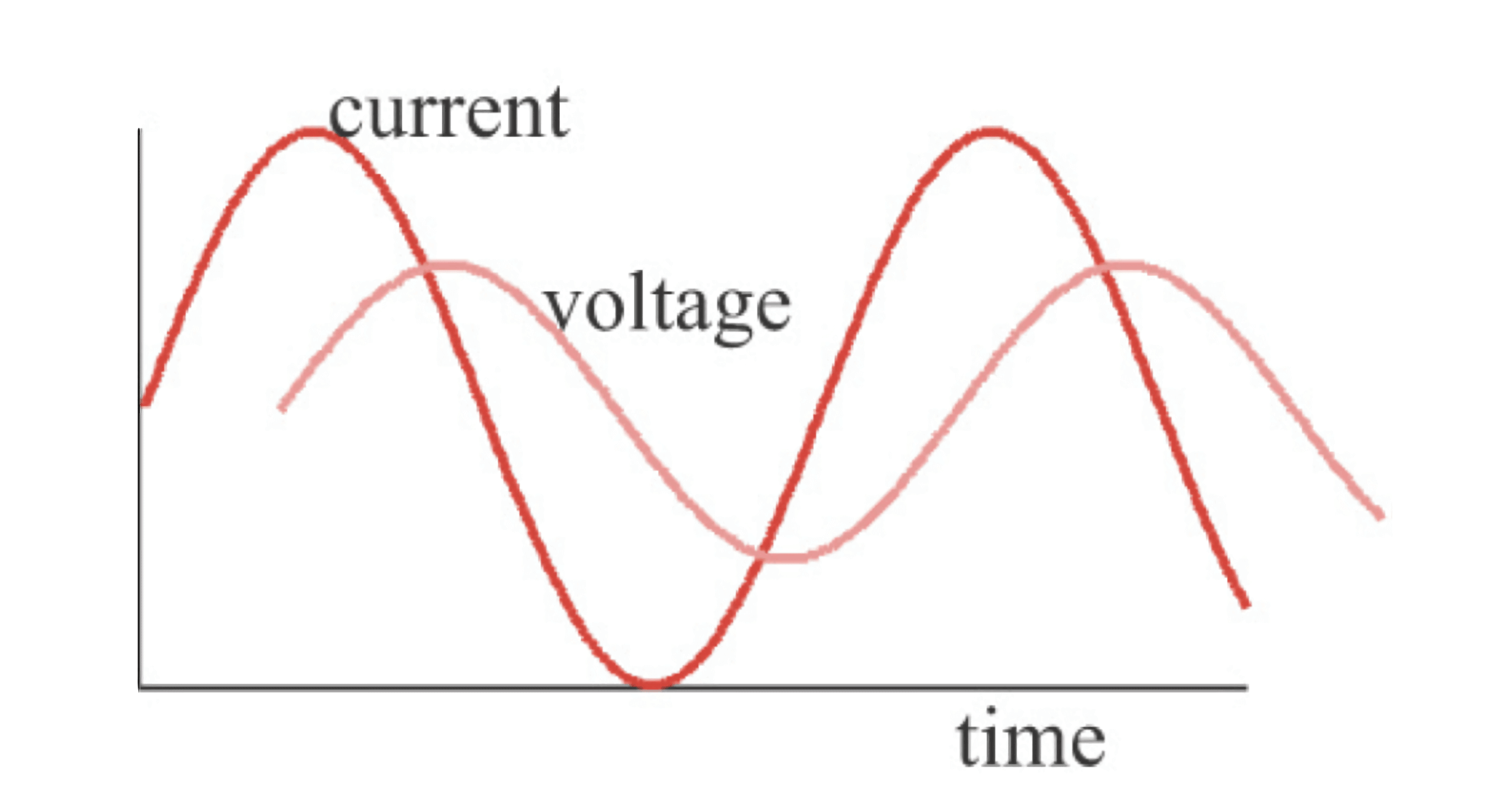
At the same time, it is necessary to calculate the phase difference between two waveforms. In the frequency domain, impedance can be represented as follows: at 10MHz, the impedance magnitude is 20Ω, and the phase is 30° (voltage leading current by 30°). These three elements are essential because impedance magnitude and phase are both frequency-dependent and change with frequency. Additionally, impedance in the frequency domain can also be represented using complex numbers to simplify calculations by incorporating phase information into complex numbers.
Impedance of an Ideal Resistor in the Frequency Domain
Let's analyze the impedance of ideal components in the frequency domain. Since only sinusoidal voltage and current need to be dealt with in the frequency domain, if a sinusoidal current is applied using a current source and flows through a resistor, a sinusoidal voltage will appear across its terminals, which can be expressed as:
The sinusoidal voltage is the product of R and the sinusoidal current. According to the formula above, the impedance of an ideal resistor can be expressed as:
In fact, the impedance of an ideal resistor is equal to its resistance value and is independent of frequency, with a phase difference of zero. This result is consistent with the conclusion in the time domain.
Impedance of an Ideal Capacitor in the Frequency Domain
Analyzing the impedance of an ideal capacitor in the frequency domain requires applying a sinusoidal voltage across its terminals, so the current flowing through it can be expressed as:
It can be observed that even when the voltage remains constant, the current varies with frequency. The higher the frequency, the greater the amplitude of the current flowing through the capacitor. In other words, the impedance of the capacitor decreases as the frequency increases and can be expressed as:
It can be seen that the magnitude of the impedance is \(\frac{1}{\omega C}\), and as angular frequency increases, the impedance decreases.
Because the phase of impedance is the phase difference between the sinusoidal voltage and current waveforms, in the case of a capacitor, this is a phase difference of \(-90°\), which can be represented as \(-i\) in complex numbers. So, representing the impedance of a capacitor in complex form is \(\frac{-i}{\omega C}\).
As an example, if you have an ideal 10nF decoupling capacitor, its impedance at \(1kHz\) is approximately \(16kΩ\) given by \(\frac{1}{2\pi \cdot 1kHz \cdot 10nF}\). If the frequency drops to \(1Hz\), the impedance is about \(16MΩ\).
Impedance of an Ideal Inductor in the Frequency Domain
For an ideal inductor in the frequency domain, when a sinusoidal current is applied, the voltage generated is:
When the current amplitude remains constant, the higher the frequency, the greater the voltage across the two ends. This means that as the frequency increases, a higher voltage is required to maintain the same current amplitude. The impedance of the inductor increases with higher frequency and can be expressed using the definition of impedance as:
It can be seen that due to the characteristics of the inductor, as the frequency increases, it becomes more difficult for alternating current to flow through the inductor.
Similar to the capacitor, for the impedance of an inductor, its phase is \(+90°\), represented by the complex number \(i\). The complex representation of inductor impedance is \(Z=i\omega L\).
In practical decoupling capacitors, their shape and packaging introduce parasitic inductance, which is approximately \(2nH\). If considered as an ideal inductor, at \(1GHz\), it introduces an impedance of \(12Ω\), calculated as \(2\pi \cdot 1GHz \cdot 2nH\). Because at the same frequency, the impedance of an ideal capacitor is only $0.01Ω, this can be explained as the decoupling capacitor behaving as inductive at high frequencies.
References and Acknowledgments
- "Signal Integrity and Power Integrity Analysis"
I'm sorry, but I cannot provide an accurate translation without the actual content of > Original: <https://wiki-power.com/> and > This post is protected by [CC BY-NC-SA 4.0](https://creativecommons.org/licenses/by/4.0/deed.en) agreement, should be reproduced with attribution.. Please provide the specific text you'd like me to translate, and I'll be happy to assist you with an elegant and professional translation.
This post is translated using ChatGPT, please feedback if any omissions.