Signal Integrity - Distortion 🚧
Signal distortion on a single network can be divided into three aspects: reflection, signal quality issues, and timing errors.
Reflection
The fundamental cause of reflection is the instantaneous impedance change in the direction of the signal propagation. Possible sources of impedance change include: the end of the interconnect line, changes in the cross-sectional area of the wiring, layer changes, gaps on the return path plane, additional components such as connectors, and wiring topology.
Sources of Reflection
Reflection at Impedance Discontinuities
When there is an abrupt change in the instantaneous impedance on a transmission line, part of the signal will reflect in the opposite direction, while the other part will continue to propagate with a changed amplitude. The magnitude of the reflected signal depends on the change in instantaneous impedance. Assuming the instantaneous impedance in the first region is \(Z_1\) and in the second region is \(Z_2\), the ratio of the reflected signal to the incident signal (reflection coefficient) is:
It can be seen that the greater the difference in impedance between the two regions, the larger the reflected signal. For example, if a 1V signal propagates along a transmission line with a characteristic impedance of 50Ω and enters a region with a characteristic impedance of 75Ω, the calculated reflection coefficient is 20%, which means the reflected voltage is 0.2V.
Reflection at Resistive Loads
There are three special cases for terminating a transmission line: open circuit, short circuit, and matched termination. Assuming the characteristic impedance of the transmission line is 50Ω and the incident voltage is 1V.
In the case of an open circuit termination, the instantaneous impedance at the end is infinitely large, and the reflection coefficient approaches 1. This means that all the incident signals will reflect back along the source path. The sum of the voltages of the incident wave and the reflected wave at the open circuit termination is 2V.
In the case of a short circuit termination (shorted to the return path), the end impedance is 0, and the reflection coefficient is -1. When the incident signal reaches the far end, it will generate a -1V reflected signal propagating towards the source end, so the voltage at this point is 0.
In the case of termination impedance matching the characteristic impedance (i.e., the termination impedance is also 50Ω), the reflection coefficient is 0. This means that there is no reflected voltage, and the voltage at the termination is only the incident signal.
In general (with a 50Ω impedance), the relationship between the impedance of region 2 and the reflection coefficient is roughly as shown in the following figure:
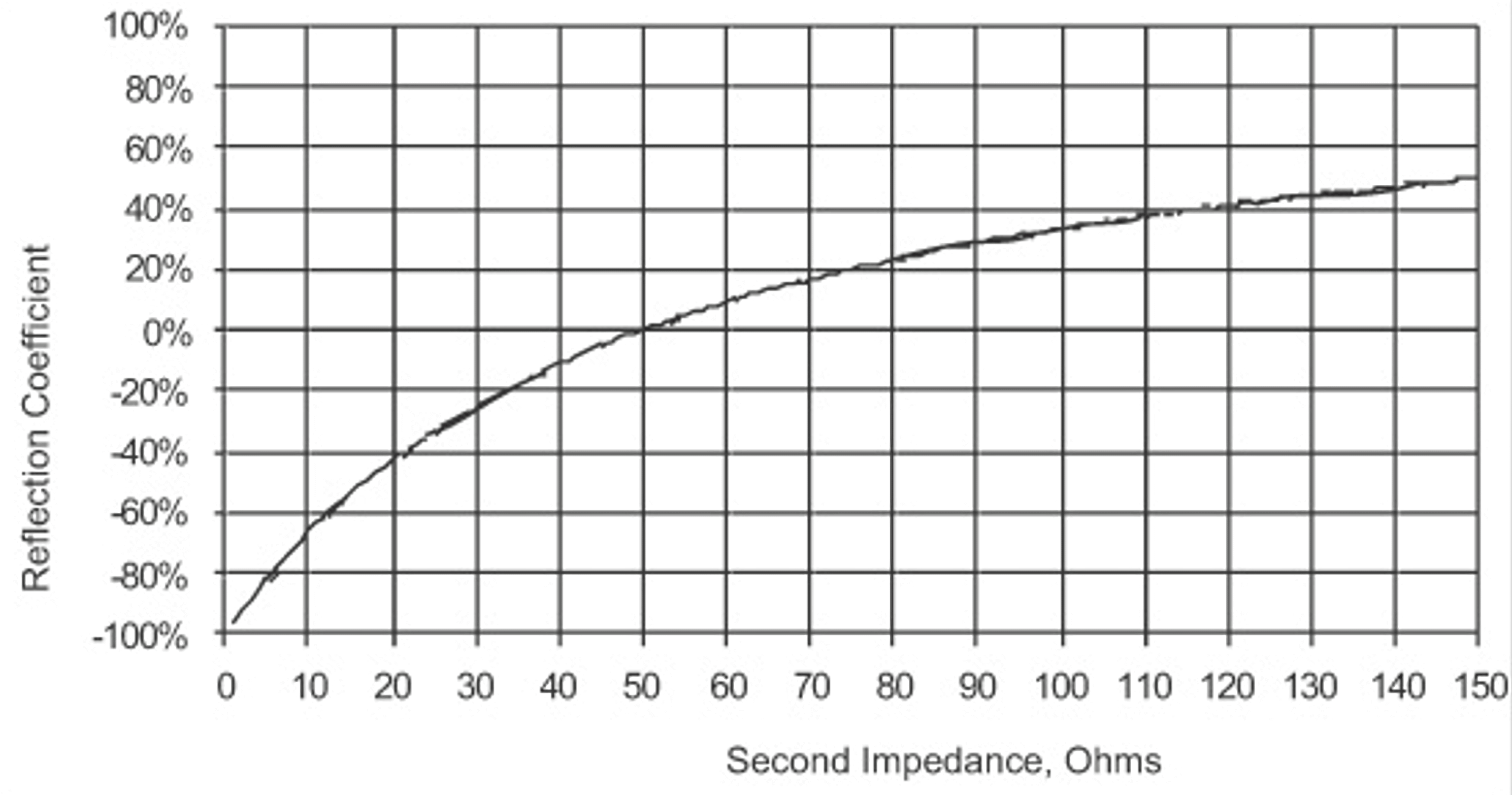
When the impedance of region 2 is smaller than that of region 1, the reflection coefficient is negative, and the reflected voltage is negative. Assuming the termination impedance is 25Ω, the reflection coefficient is -0.33, so there is a -0.33V voltage reflected back to the source end, and the actual voltage at the termination is 1+(-0.33)=0.67V.
Reflection Plot
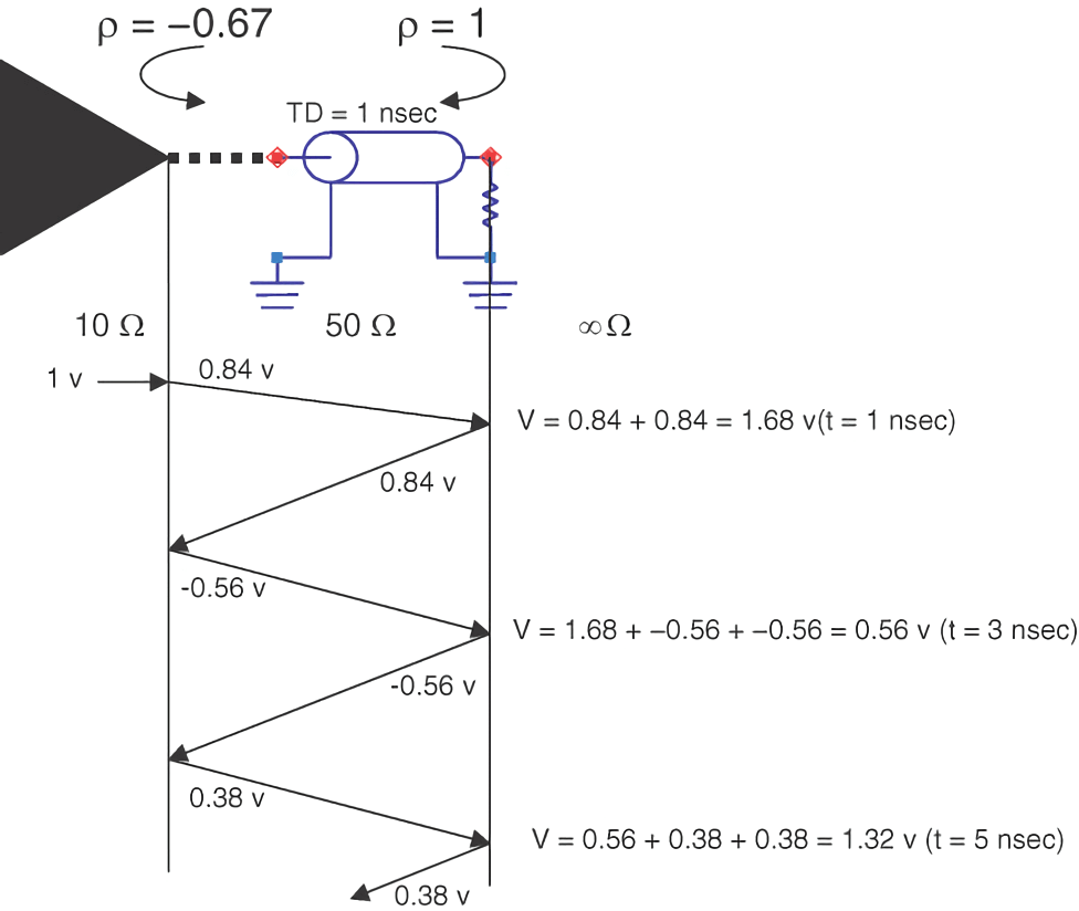
If the transmission line delay, the impedance of each region through which the signal passes, and the initial voltage of the driver are known, the voltage at each reflection surface / at any given time can be calculated.
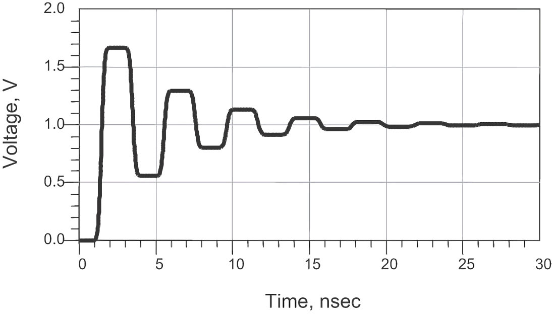
Assuming a driver source voltage of 1V, internal resistance of 10Ω, and an open circuit termination at the end of the transmission line, the following reflection plot and curve can be obtained based on the reflection formula:
Manifestations of Reflection
Reflection is usually manifested as overshoot, undershoot, and ringing.
Overshoot
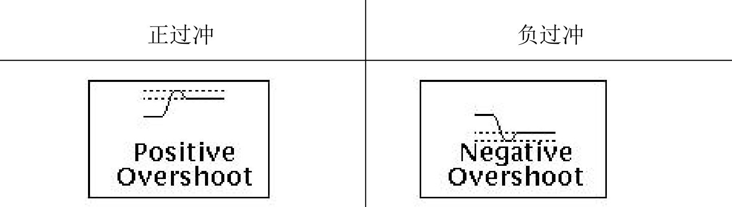
Overshoot refers to the first peak of oscillation and can be positive or negative. The danger is that it may cause damage to the components (greater than VCC or less than GND). In addition, positive overshoot can become a source of interference, causing crosstalk to other components; negative overshoot causes a negative voltage on the pins, biasing the PN substrate (parasitic diode) of the device forward, and the high current may cause fuse blowout resulting in an open circuit.
Ringing
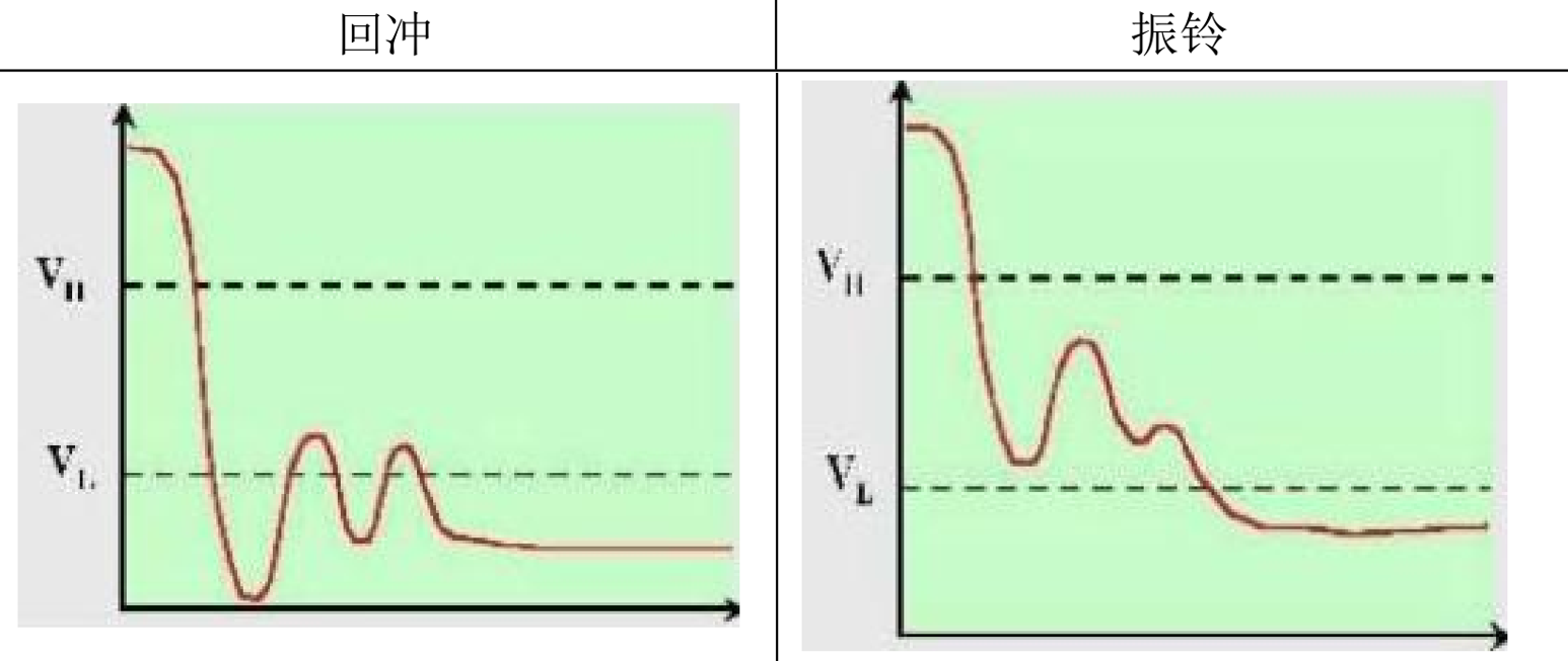
Ringing refers to multiple crossings of the threshold level, while overshoot refers to multiple repetitions before returning to the normal level.
The hazards of ringing are similar to multiple overshoots, creating an uncertain state between high and low levels. The cause of ringing is improper impedance matching (either too large or too small).
Solutions to Reflection
The solution to reflection is to try to keep the impedance of the interconnect line constant. Specific measures include:
- Ensuring consistent impedance of the interconnect line.
- Properly terminating the transmission line to match the characteristic impedance.
- Minimizing impedance discontinuities, such as changes in cross-sectional area, layer changes, and gaps on the return path plane.
- Using appropriate additional components, such as connectors, to maintain impedance continuity.
- Designing a proper wiring topology to minimize impedance variations.
By implementing these measures, the reflection issues can be effectively addressed and signal integrity can be improved.
Translate into English:
- Use controlled impedance interconnects.
- Increase resistance matching, with the reference practice being series resistors at the beginning or parallel resistors at the end.
- Adopt wiring rules that maintain constant impedance along the line topology and minimize branch length.
- Fine-tune the geometric characteristics of the lines, such as avoiding right angles or sharp angles.
- PCB routing should avoid interference sources and coupling paths.
Timing Errors
The time delay difference between two or more signal paths is called skew. When there is unexpected skew between signal lines and clock lines, it may result in false triggering and logic errors. When there is skew in differential lines, some query signals may become common-mode signals, causing distortion.
References and Acknowledgements
- "Signal Integrity and Power Integrity Analysis"
- "Signal Integrity Revealed - Dr. Yu's SI Design Notes"
- What Every PCB Designer Should Know - Crosstalk Explained (with Eric Bogatin)
- "Hardware Signal Quality SI Test Specification"
- Transmission Line Crosstalk Analysis
Original: https://wiki-power.com/ This post is protected by CC BY-NC-SA 4.0 agreement, should be reproduced with attribution.
Unfinished draft 🚧:
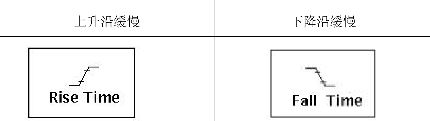
The slow generation of signal edges can also be caused by insufficient driving capability or excessive load (such as too high link impedance).
The methods to solve the slow generation of signal edges are:
- Increase driving capability.
- Reduce the load.
Due to insufficient driving or excessive load, the slow generation of signal edges is often accompanied by a low signal amplitude.
Rise Edge Degradation
Adverse Effects of Lossy Lines
After a signal with fast-changing edges passes through a certain length of transmission line, the rise edge will be elongated:
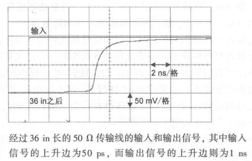
The signal quality issues caused by rise edge degradation are due to frequency-dependent losses in the wire/dielectric. These losses are greater at high frequencies than at low frequencies, resulting in slow signal edges. When the rise edge degrades to near the unit interval of the signal, 1 bit of information will leak into the next or even several bits, causing data sampling errors. This effect is called intersymbol interference (ISI) and is the main cause of problems when the data rate is greater than or equal to 1Gbps.
If the rise edge degradation causes the rise edge to elongate close to the unit interval, intersymbol interference may occur:
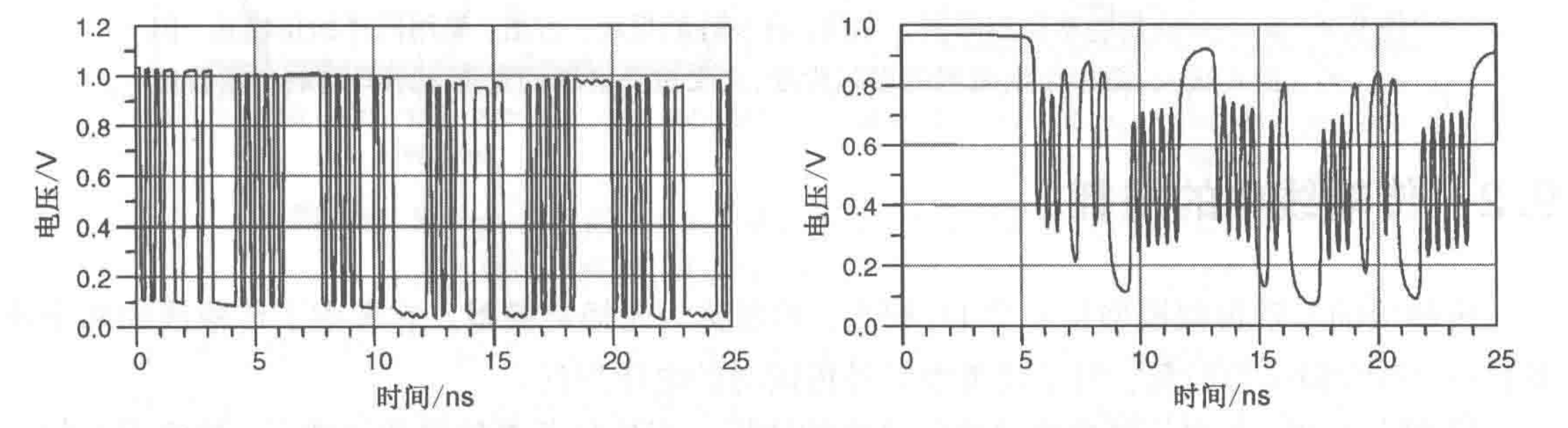
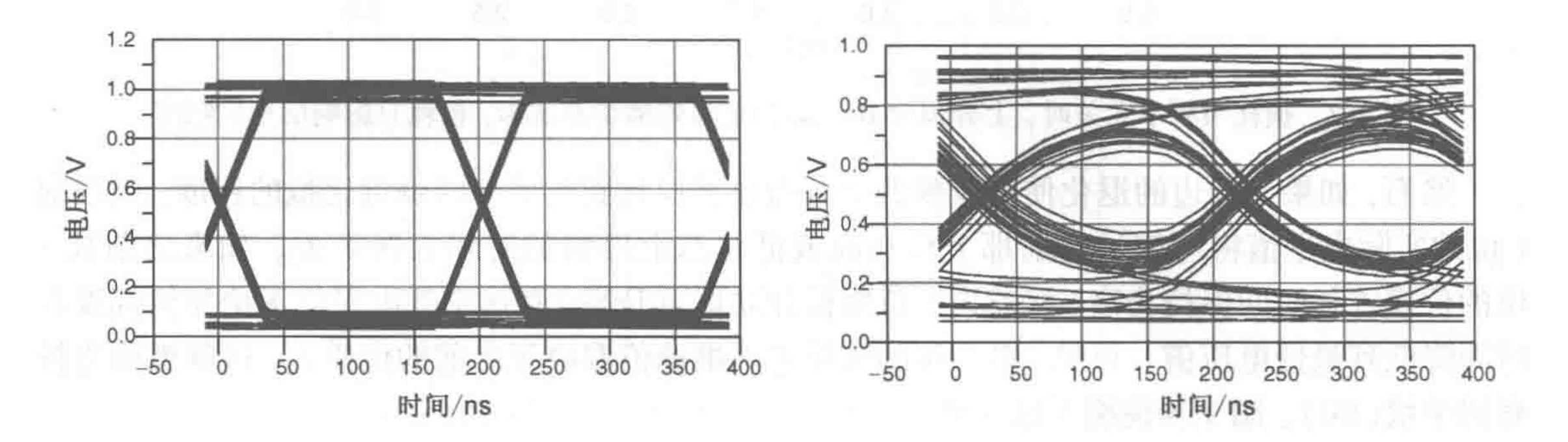
The quality of high-speed signals can be evaluated using an eye diagram, which can measure the bit error rate (the left diagram shows slight loss, while the right diagram shows significant loss):
Losses in Transmission Lines
When a signal propagates along a transmission line, there are five ways in which energy is lost at the receiving end:
- Radiation loss
- Coupling to adjacent traces
- Impedance mismatch
- Wire resistance
- Dielectric loss
Wire Resistance (Wire Resistance and Skin Effect)
This post is translated using ChatGPT, please feedback if any omissions.