المكونات الأساسية - المقاومة
اختيار المقاومة
عمومًا ، يجب مراعاة العوامل الأربعة التالية:
- قيمة المقاومة: تعتمد على احتياجات الدائرة الكهربائية المحددة
- الدقة: عادة ما تكون 1٪ ، إذا كانت مستخدمة في دائرة كشف التيار (Rsense) ، فإن قيمة المقاومة المنخفضة والقدرة العالية تعطي دقة أعلى
- القدرة الاسمية: تلبي 50٪ من التقليل ، يرجى الرجوع إلى الجدول أدناه لمعرفة القدرة المقابلة لكل حزمة
- الحجم: الحجم يتعلق بالقدرة ، يجب مراعاة القدرة وصعوبة التصنيع
- درجة الحرارة والرطوبة وما إلى ذلك: العوامل التي يجب مراعاتها في حالات معينة
- انحراف الحرارة: يجب مراعاته إذا كانت تستخدم للدقة العالية (تطبيقات الاستشعار)
معلمات الحزمة السطحية
| النظام الإمبراطوري | النظام المتري | الطول (مم) | العرض (مم) | الارتفاع (مم) | القدرة الاسمية (واط) | الجهد الكهربي (فولت) |
|---|---|---|---|---|---|---|
| 0201 | 0603 | 0.60±0.05 | 0.30±0.05 | 0.23±0.05 | 1/20 | 25 |
| 0402 | 1005 | 1.00±0.10 | 0.50±0.10 | 0.30±0.10 | 1/16 | 50 |
| 0603 | 1608 | 1.60±0.15 | 0.80±0.15 | 0.40±0.10 | 1/10 | 50 |
| 0805 | 2012 | 2.00±0.20 | 1.25±0.15 | 0.50±0.10 | 1/8 | 150 |
| 1206 | 3216 | 3.20±0.20 | 1.60±0.15 | 0.55±0.10 | 1/4 | 200 |
| 1210 | 3225 | 3.20±0.20 | 2.50±0.20 | 0.55±0.10 | 1/3 | 200 |
| 1812 | 4832 | 4.50±0.20 | 3.20±0.20 | 0.55±0.10 | 1/2 | 200 |
| 2010 | 5025 | 5.00±0.20 | 2.50±0.20 | 0.55±0.10 | 3/4 | 200 |
| 2512 | 6432 | 6.40±0.20 | 3.20±0.20 | 0.55±0.10 | 1 | 200 |
قيمة المقاومة
طرق التعبير عنها على الدائرة المطبوعة
- طريقة الأرقام الثلاثة: \(XXY = XX * 10^Y\)
- على سبيل المثال ، إذا كانت القيمة المطبوعة هي 272 ، فإن القيمة الفعلية للمقاومة هي \(27 * 10^2=27 * 100=2.7k\)
- طريقة الأرقام الأربعة: \(XXXY = XXX * 10^Y\)
- طريقة الحروف لتحديد موضع الفاصلة العشرية: يستخدم الحرف
Rلتحديد موضع الفاصلة العشرية.- على سبيل المثال ، إذا كانت القيمة المطبوعة هي 5R6 ، فإن القيمة الفعلية للمقاومة هي 5.6 Ω
- يمكن أيضًا استخدام الحروف
Mوkوmلتحديد موضع الفاصلة العشرية ، وتمثل على التواليMΩوkΩوmΩ
- طريقة رموز ثلاثة أرقام للضرب: في
XXY، يشيرXXإلى رمز الرقم الصحيح ، وYيشير إلى قوة 10 ، يرجى الرجوع إلى الجدول أدناه للحصول على القيم المعتادة للمقاومة
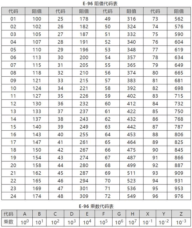
القيم المعتادة للمقاومة
وفقًا للمعايير المتفق عليها ، يتم استخدام سلسلة E96 بشكل عام ، وتشمل القيم المعتادة ورموز الضرب في الجدول أدناه:
فشل المقاومة
وفقًا لترتيب الاحتمالية المحتملة ، فإنها تشمل:
- فتح الدائرة: عيوب في طبقة المقاومة أو تدهورها ؛ قد يحدث عندما يكون هناك صدمة لحظية بقدرة عالية
- انحراف قيمة المقاومة عن المواصفات: قد يحدث بعد الشيخوخة
- كسر الأرجل: عيوب في عملية اللحام ، أو تلوث النقاط ؛ قد يحدث عندما يتم ثني أرجل المقاومة المثبتة بالقابس بشكل متكرر
- احتراق: قد يحدث عندما يعمل لفترة طويلة بقدرة تفوق القدرة الاسمية ، مما يؤدي إلى فتح الدائرة
- مشاكل اللحام: مشاكل مثل اللحام الزائف
- كسر الأسلاك وفتح الدائرة: قد يحدث عند تعرضه للإجهاد الميكانيكي أو صدمة زائدة للطاقة لفترة قصيرة
استخدام المقاومة بقيمة صفر أوم
- When used as a jumper, it crosses over areas where no lines are laid.
- Used as a shorting socket.
- Single-point connection of digital ground and analog ground (sometimes also using inductors or magnetic beads).
- Reserved resistance for debugging.
Overcurrent capability of 0-ohm resistors with different packages (generally used with a 50% reduction in rated current):
| Package | Rated Current (Maximum Current) / A |
|---|---|
| 0201 | 0.5 (1) |
| 0402 | 1 (2) |
| 0603 | 2 (3) |
| 0805 and up | 2 (5) |
Usage scenarios for resistors
Voltage Divider Circuit
Resistors are connected in series for voltage division, with the following circuit characteristics:
- The current through each resistor is the same, i.e., the current in each resistor is equal, i.e., \(I = I_1 = I_2 = I_3\).
- The total voltage is equal to the sum of the voltage drops across each resistor, i.e., \(V = V_1 + V_2 + V_3\).
- The total resistance is equal to the sum of the resistances, i.e., \(R = R_1 + R_2 + R_3\).
For example, the feedback pin of a voltage regulator is generally connected to a voltage divider circuit composed of two resistors, which provides an output voltage value close to the internal reference voltage.
Current Divider Circuit
Resistors are connected in parallel for current division, with the following circuit characteristics:
- The voltage across each branch is equal.
- The total current is equal to the sum of the branch currents, i.e., \(I = I_1 + I_2 + I_3\).
- The reciprocal of the total resistance is equal to the sum of the reciprocals of the branch resistances, i.e., \(\frac{1}{R} = \frac{1}{R_1} + \frac{1}{R_2} + \frac{1}{R_3}\).
In practical circuit design, it is often used to connect in parallel between the collector and emitter of a transistor as a protective resistor. In some cases where the power of a linear power regulator is insufficient, a resistor can also be connected between the input and output terminals to increase the output current.
Current Limiting Circuit
Generally used for current limiting of LEDs. A resistor is connected in series with the circuit where the LED is located to determine the resistance value based on the forward voltage drop of the LED (generally 0.7 V) and the rated current of the LED. It should be noted that the calculated actual operating current should be smaller than the rated operating current of the LED.
Current limiting circuits can also be used in hot-swappable circuits.
Impedance Matching Circuit
The purpose of impedance matching is to allow the load to obtain maximum power, i.e., the load resistance is equal to the source resistance. The derivation process is as follows:
Assuming the load resistance is R, the electromotive force of the power source is U, and the internal resistance is r, the current through R is:
It can be seen that the smaller R is, the larger the current. The voltage across R is:
The larger R is, the larger the output voltage \(U_R\) is. The power of R is:
Since r is constant, when R=r, \(\frac{(R-r)^2}{R}=0\), and the maximum power \(P_{max}=\frac{U^2}{4r}\) can be obtained.
RC Charging and Discharging Circuit
\(\tau=RC\) (if the units of R and C are Ω and F, the unit of the result is s).
The RC circuit can be regarded as a delay circuit or a filtering circuit, which filters both the rising and falling edges of the pulse signal, making it smooth. Different rise times can be achieved by adjusting the values of R and C.
Pull-up and Pull-down Circuit
Pull-up is used to clamp an uncertain signal to a high level (while also acting as a current limiter); pull-down is the opposite.
Generally, resistors below 50 Ω are strong pull-up/pull-down, and resistors above 100 kΩ are weak pull-up/pull-down.
Other Circuits
- Peripheral circuits of operational amplifiers.
- Interference suppression circuits to improve surge voltage capability.
- Load circuits (to prevent circuit open circuit).
References and Acknowledgments
- "《مائة ألف سؤال حول الأجهزة - الجزء الخاص بالأجهزة الغير نشطة》"
- جدول مقابلة حجم وقدرة مكثفات المقاومة السطحية
- دورة متخصصة في مجال مزودات الطاقة (الجزء 2) | أمور صغيرة عن المقاومة والتكثيف لا تعرفها
عنوان النص: https://wiki-power.com/ يتم حماية هذا المقال بموجب اتفاقية CC BY-NC-SA 4.0، يُرجى ذكر المصدر عند إعادة النشر.
تمت ترجمة هذه المشاركة باستخدام ChatGPT، يرجى تزويدنا بتعليقاتكم إذا كانت هناك أي حذف أو إهمال.