ADC - Dynamic Parameters
This post was originally written in English.
Dynamic Parameters
ADC's dynamic parameters mainly contain:
- Signal to Noise Ratio (SNR)
- Total Harmonic Distortion (THD)
- Signal to Noise and Distortion Ratio (SINAD)
- Inter-modulation Error (IM)
Signal to Noise Ratio (SNR)
Signal to Noise Ratio (SNR) of an ADC is defined as the ratio of the Measured Signal Power's RMS (excluding Harmonic Distortion) to the Noise Power's RMS:
Since SNR is an ratio of power, \(20\) in the equation means the square of the ratio of voltage.
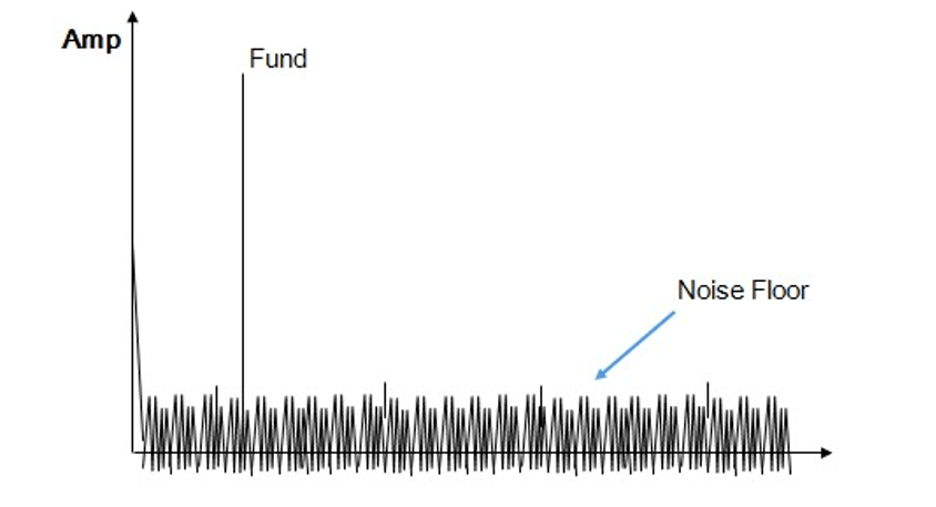
Although the Harmonic Distortion is not included in the measurement of SNR, but the Quantization, Thermal and other residual noise in converter are included.
Total Harmonic Distortion (THD)
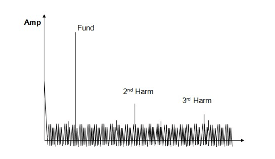
Total Harmonic Distortion (THD) of an ADC is defined as the ratio of the fundamental to all the harmonic distortion:
How to Test Dynamic Parameters
Test System Setup
Test system setup for ADC dynamic parameter tests:
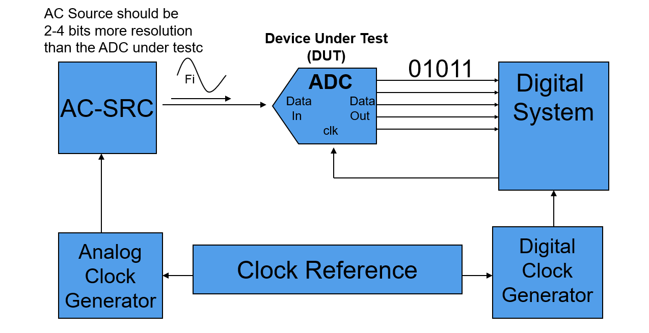
Resolution of AC SRC should be at least 2 to 4 bits better than DUT.
Tests Concept
ADC has a theoretical best ever SNR of:
Where \(N\) is the number of ADC's bits.
Procedure of testing the dynamic parameters of an ADC DUT is listed below.
1. Make a continuous input signal with the tester for the ADC to convert
It is common practice to ensure that the analog/digital clock are referenced to a common master clock, so that the relationship of the clock sources's frequency is fixed and synchronized, which making test results highly repeatable.
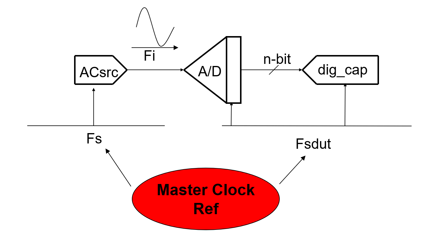
2. Collect a set of samples with the ADC coherently
For AC Source:
Where \(Fs\) is the samping rate of AC Source, \(Fi\) is signal frequency, \(Ns\) is the number of samples (does not have to be a 2x number), \(Ms\) is the number of integer cycles (does not have to be odd).
For Digital Capture:
Where \(Fs(dut)\) is the ADC sampling rate also the Digital Capture's sample rate, \(Fi\) is the signal frequency, \(Ncap\) is the number of samples captured (2x number), \(Mc\) is the number of integer cycles (odd).
3. Send the collected set of time samples to the DSP to perform DFT / FFT analysis
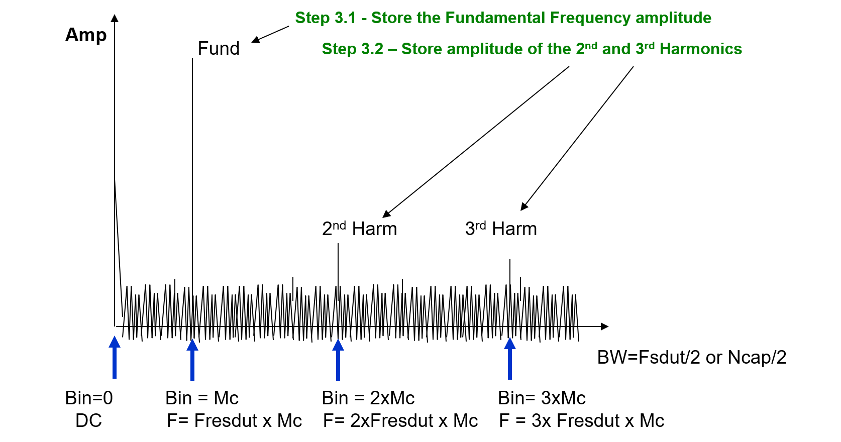
?
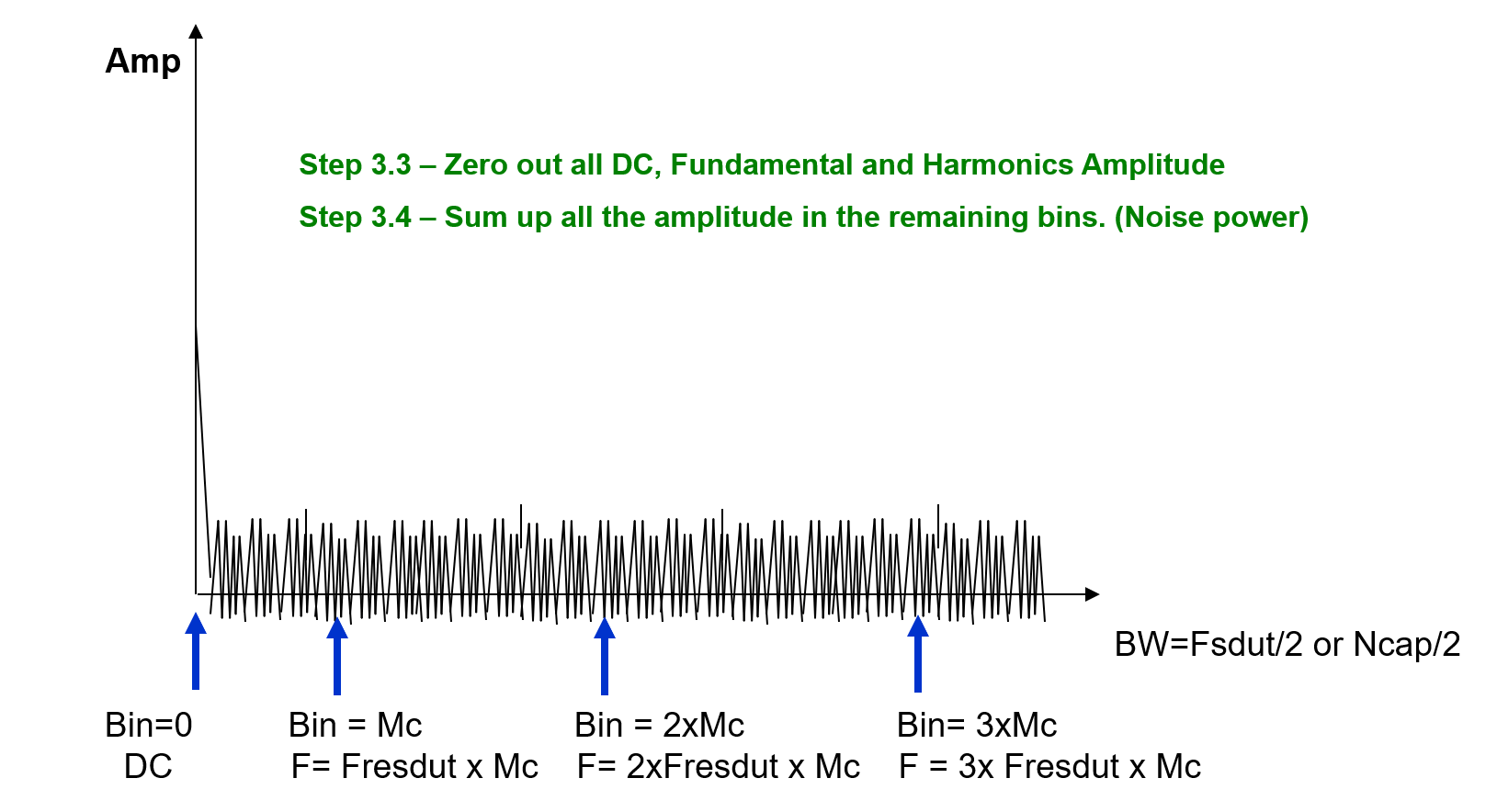
4. Analyze the frequency bins of interest using equations or tester algorithms for SNR, THD and compare to specification
5. Make a pass / fail decision based on the results
References & Acknowledgements
- Fundamentals of Testing Using ATE
- The-Fundamentals-of-Mixed-Signal-Testing_Brian-Lowe
Original: https://wiki-power.com/
This post is protected by CC BY-NC-SA 4.0 agreement, should be reproduced with attribution.